Installation Instructions POINT I/O 24V dc Expansion Power Supply Catalog Number 1734-EP24DC, Series B Inside . . .
POINT I/O 24V dc Expansion Power Supply Important User Information Solid state equipment has operational characteristics differing from those of electromechanical equipment. Safety Guidelines for the Application, Installation and Maintenance of Solid State Controls (Publication SGI-1.1 available from your local Rockwell Automation sales office or online at http://www.literature.rockwellautomation.
POINT I/O 24V dc Expansion Power Supply 3 Preventing Electrostatic Discharge ATTENTION This equipment is sensitive to electrostatic discharge, which can cause internal damage and affect normal operation. Follow these guidelines when you handle this equipment: • Touch a grounded object to discharge potential static. • Wear an approved grounding wriststrap. • Do not touch connectors or pins on component boards. • Do not touch circuit components inside the equipment.
POINT I/O 24V dc Expansion Power Supply Environment and Enclosure ATTENTION This equipment is intended for use in a Pollution Degree 2 industrial environment, in overvoltage Category II applications (as defined in IEC publication 60664-1), at altitudes up to 2000 meters without derating. This equipment is considered Group 1, Class A industrial equipment according to IEC/CISPR Publication 11.
POINT I/O 24V dc Expansion Power Supply 5 North American Hazardous Location Approval The following information applies when operating this equipment in hazardous locations: Informations sur l’utilisation de cet équipement en environnements dangereux: Products marked “CL I, DIV 2, GP A, B, C, D” are suitable for use in Class I Division 2 Groups A, B, C, D, Hazardous Locations and nonhazardous locations only.
POINT I/O 24V dc Expansion Power Supply European Hazardous Location Approval European Zone 2 Certification (The following applies when the product bears the EEx marking.) This equipment is intended for use in potentially explosive atmospheres as defined by European Union Directive 94/9/EC.
POINT I/O 24V dc Expansion Power Supply 7 ATTENTION ATTENTION ATTENTION Do not connect 120/240V ac to the 1734-EP24DC terminals. Damage to the supply will result. Use the 1734-EP24DC expansion power supply only with 1734 POINT I/O adapters, such as the 1734-ADN DeviceNet adapter. POINT I/O is grounded through the DIN rail to chassis ground. Use zinc plated yellow-chromate steel DIN rail to assure proper grounding. The use of other DIN rail material (e.g., aluminum, plastic, etc.
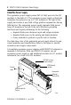
POINT I/O 24V dc Expansion Power Supply About the Power Supply The expansion power supply passes 24V dc field power to the I/O modules to the right of it. The expansion power supply extends the backplane bus power for up to 17 I/O modules to the right of the supply and creates a new field voltage partition segment for driving field devices.
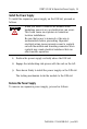
POINT I/O 24V dc Expansion Power Supply 9 Install the Power Supply To install the expansion power supply on the DIN rail, proceed as follows. WARNING When you insert or remove the module while backplane power is on, an electrical arc can occur. This could cause an explosion in hazardous location installations. Be sure that power is removed or the area is nonhazardous before proceeding. Repeated electrical arcing causes excessive wear to contacts on both the module and its mating connector.
POINT I/O 24V dc Expansion Power Supply 1. Pull up on the RTB removal handle to remove the terminal block. 42511 2. Remove the module to the right of the 1734-EP24DC module from its base unit. 3. Use a small-bladed screwdriver to rotate the DIN rail locking screw to a vertical position. This releases the locking mechanism. 4. Lift straight up to remove. Replace the Power Supply To install a replacement expansion power supply, proceed as follows.
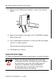
POINT I/O 24V dc Expansion Power Supply 11 1. Remove the module to the right of the power supply from its base unit. 2. Position the power supply vertically above the DIN rail. 3. Slide the power supply down allowing the interlocking side pieces to engage the adjacent modules (both left and right sides). 4. Press firmly to seat the power supply on the DIN rail. The power supply locking mechanism snaps into place. 5. Reinsert the module into the base next to the expansion power supply.
POINT I/O 24V dc Expansion Power Supply NC NC CHAS GND NC = No Connection CHAS GND = Chassis Ground C = Common V = Supply CHAS GND C C V V 41970 12/24Vdc Wiring 0 1 NC NC 2 3 CHAS CHAS GND GND 4 12/24V dc 5 C C V V This supply will be connected to the internal field power bus. V dc Do not connect 120/240V ac power to this supply.
POINT I/O 24V dc Expansion Power Supply 13 Connect Terminal Terminals (for continuing power) +V dc 6 7 -V dc 4 5 Chas Gnd 2 3 12/24V dc becomes the internal field power bus for modules to the right.
POINT I/O 24V dc Expansion Power Supply Example of Functional Partitioning EP24DC ADN I B 2 Adapter Status DeviceNet Status PointBus Status I B 4 1734-ADN O B 2 E O B 4 E System Power I E 2 C I E 2 C O E 2 C 1734-EP24DC System Power r DeviceNet Power DeviceNet Power 0 1 0 1 0 1 0 1 0 1 0 1 0 1 0 1 1 12/24V dc Analog Supply 12/24V dc Digital Supply 1734adn4 Publication 1734-IN058B-EN-P - June 2005
POINT I/O 24V dc Expansion Power Supply 15 Example of Logical Partitioning EP24DC ADN I E 2 C Adapter Status DeviceNet Status PointBus Status 1734-ADN O E 2 C I B 2 O B 2 E I B 2 O B 2 E O B 4 E 1734-EP24DC System Power r DeviceNet Power Status Power DeviceNet Power 0 1 0 1 0 1 0 1 0 1 0 1 0 1 0 1 1 12V dc Supply 24V dc Supply 1734adn4 Publication 1734-IN058B-EN-P - June 2005
POINT I/O 24V dc Expansion Power Supply Specifications 1734-EP24DC POINT I/O 24V dc Expansion Power Supply Specification Value I/O Module Capacity 4-17 modules, depending on current rating of each module Input Voltage Rating 24V dc nominal 10…28.8V dc range Field Side Power Requirements 24V dc (+20% = 28.
POINT I/O 24V dc Expansion Power Supply 17 General Specifications Specification Value Power Consumption 9.8 W maximum @ 28.8V dc Power Dissipation 3.0 W maximum @ 28.8V dc Thermal Dissipation 10.0 BTU/hr maximum @ 28.8V dc Isolation Voltage (continuous-voltage withstand rating) 50V continuous Tested to withstand 2600V dc for 60 s Field Power Bus Supply Voltage Voltage Range Supply Current 24V dc nominal 10…28.
POINT I/O 24V dc Expansion Power Supply Environmental Specifications Emissions CISPR 11: Group 1, Class A ESD Immunity IEC6100-4-2 6 kV contact discharges 8 kV air discharges Radiated RF Immunity IEC 61000-4-3 10V/m with 1 KHz sine-wave 80% AM from 30 MHz to 2000 MHz 10V/m with 200 Hz 50% Pulse 100% AM at 900 MHz 10V/m with 200 Hz 50% Pulse 100% AM at 1890 MHz EFT/B Immunity IEC 61000-4-4 +4 kV at 2.
POINT I/O 24V dc Expansion Power Supply 19 Environmental Specifications Current Derating for Mounting 1.3 1.0 Current Horizontal - 1A @ (10-19.2V); 1.3A @ (19.2-28.8) Vertical - 1A @ (10-28.8V) 0.5 10 19.2 Voltage 28.
Certifications Certifications1 (when product is marked) 1 c-UL-us UL Listed Industrial Control Equipment, certified for U.S. and Canada c-UL-us UL Listed for Class I, Division 2, Group A,B,C,D Hazardous Locations, certified for U.S. and Canada CE European Union 89/336/EEC EMC Directive, compliant with: EN 50082-2; Industrial Immunity EN 61326; Meas./Control/Lab.