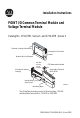
Installation Instructions POINT I/O Common Terminal Module and Voltage Terminal Module Catalog No. 1734-CTM, Series C, and 1734-VTM, Series C Module Locking Mechanism Insertable I/O Module Module Wiring Diagram DIN Rail Locking Screw (orange) Mechanical keying (orange) RTB Removable Handle Removable Terminal Block (RTB) Interlocking Side Pieces 31538-M Mounting Base The Wiring Base Assembly consists of Mounting Base, 1734-MB, and Removable Terminal Block, 1734-RTB or 1734-RTBS.
POINT I/O Common Terminal Module and Voltage Terminal Module Important User Information Solid state equipment has operational characteristics differing from those of electromechanical equipment. Safety Guidelines for the Application, Installation and Maintenance of Solid State Controls (Publication SGI-1.1 available from your local Rockwell Automation sales office or online at http://literature.rockwellautomation.
POINT I/O Common Terminal Module and Voltage Terminal Module 3 WARNING Environment and Enclosure This equipment is intended for use in a Pollution Degree 2 industrial environment, in overvoltage Category II applications (as defined in IEC publication 60664-1), at altitudes up to 2000 meters without derating. This equipment is considered Group 1, Class A industrial equipment according to IEC/CISPR Publication 11.
POINT I/O Common Terminal Module and Voltage Terminal Module WARNING Explosion Hazard Do not disconnect equipment unless power has been removed or the area is known to be nonhazardous. Do not disconnect connections to this equipment unless power has been removed or the area is known to be nonhazardous. Secure any external connections that mate to this equipment by using screws, sliding latches, threaded connectors, or other means provided with this product.
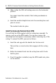
POINT I/O Common Terminal Module and Voltage Terminal Module 5 Install the Mounting Base To install the mounting base on the DIN rail, proceed as follows. 1. Position the mounting base vertically above the installed units (adapter, power supply, or existing module). 2. Slide the mounting base down so that the interlocking side pieces to engage the adjacent module or adapter. 3. Press firmly to seat the mounting base on the DIN rail. The mounting base snaps into place.
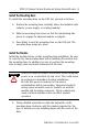
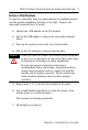
POINT I/O Common Terminal Module and Voltage Terminal Module 2. Make certain the DIN rail locking screw is in the horizontal position. You cannot insert the module if the locking mechanism is unlocked. 3. Insert the module straight down into the mounting base and press to secure. The module locks into place. Install the Removable Terminal Block (RTB) You will find the RTB supplied with the wiring base assembly. To remove, pull up on the RTB handle.
POINT I/O Common Terminal Module and Voltage Terminal Module 7 Remove a Mounting Base To remove a mounting base, you must remove any installed module, and the module installed in the base to the right. Remove the removable terminal block (if wired). 1. Unlatch the RTB handle on the I/O module. 2. Pull on the RTB handle to remove the removable terminal block. 3. Press on the module lock on the top of the module. 4. Pull on the I/O module to remove from the base.
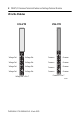
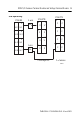
POINT I/O Common Terminal Module and Voltage Terminal Module Wire the Modules 1734-VTM 1734-CTM 0 0 1 1 1734 CTM 1734 VTM Voltage Out Voltage Out Common Common Voltage Out Voltage Out Common Common Voltage Out Voltage Out Common Common Voltage Out Voltage Out Common Common Voltage Out = 0 to 7 Common = 0 to 7 43929 Publication 1734-IN024A-EN-E - March 2005
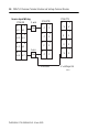
POINT I/O Common Terminal Module and Voltage Terminal Module 9 Sink Input Wiring 1734-IB8 1 0 1734-CTM 2-wire Prox In 0 In 1 2 1734-VTM 1 0 V V In 2 In 3 3-wire 7 In 7 In 6 V 5 V 4 5 4 In 4 In 5 6 V 3 V 2 3 Prox 6 7 V V V = Voltage Out 1 0 C C C C C C C C 3 2 5 4 6 7 C = Common 43927 Publication 1734-IN024A-EN-E - March 2005
POINT I/O Common Terminal Module and Voltage Terminal Module Source Input Wiring 1734-IV8 2-wire 1 0 Prox In 0 In 1 1734-CTM 1734-VTM 3 2 In 2 In 3 2 5 4 In 4 In 5 4 3-wire 6 7 In 6 In 7 C 1 C C 3 C C 5 C 0 V V 3 2 V V V V V V 5 4 6 6 Prox 1 0 7 C C C = Common 7 V = Voltage Out 43927 Publication 1734-IN024A-EN-E - March 2005
POINT I/O Common Terminal Module and Voltage Terminal Module 11 Source Output Wiring 1734-OB8 0 1 Out 0 Out 1 3 2 Out 2 Out 3 5 4 Out 5 Out 4 7 6 Out 6 Out 7 1734-CTM 0 Load 1 C C C C C C C C 2 Load 3 5 4 Load 6 Load 7 C = Common Sink Output Wiring 1734-OV8 0 Out 0 2 Out 2 4 Out 4 6 Out 6 43928 1734-VTM 1 Out 1 3 Out 3 5 Out 5 7 Out 7 0 Load 2 Load Load 4 6 Load 1 V V V V V V V V 3 5 7 V = Voltage Out 43928 Publication 1734-IN024A-EN-E - Marc
POINT I/O Common Terminal Module and Voltage Terminal Module General Purpose Wiring Adapter 1734 VTM 1734 CTM V = Voltage Out C = Common Power Supply Publication 1734-IN024A-EN-E - March 2005 Other Devices 43926
POINT I/O Common Terminal Module and Voltage Terminal Module 13 4V dc 2 Input Sink Module Cat. No. 1734-IB2 Safety Approvals North American Hazardous Location Approval The 1734-CTM and 1734-VTM modules, Series C, are North American Hazardous Location approved.
POINT I/O Common Terminal Module and Voltage Terminal Module Specifications Indicators None Keyswitch Position 5 Module Location 1734-TB or -TBS wiring base assembly Pointbus Current None Power Dissipation None Thermal Dissipation None Isolation Voltage (Continuous Voltage Withstand Rating) Tested to 1600 Vrms for 60 seconds Field Power Bus Supply Voltage Output Current Dimensions 10-28.8V dc, 120/240V ac 2A per point, 4A module max. Inches 2.2H x 0.47W x 2.
POINT I/O Common Terminal Module and Voltage Terminal Module 15 Terminal Base Screw Torque 7 pound-inches (0.8Nm) Mass 1.09 oz/30.
Rockwell Automation Support Rockwell Automation provides technical information on the web to assist you in using its products. At http://support.rockwellautomation.com, you can find technical manuals, a knowledge base of FAQs, technical and application notes, sample code and links to software service packs, and a MySupport feature that you can customize to make the best use of these tools.