Installation Instructions POINT I/O Address Reserve Module (Cat. No.
POINT I/O Address Reserve Module This Series C product can be used with DeviceNet and PROFIBUS adapters. It can be used with ControlNet and Ethernet adapters using RSLogix 5000, version 11 (or higher) software. General The 1734-ARM address reserve module retains a node address for later insertion of any future option. It can be installed in any slot with any key position. However, we recommend that the key position be that of the module that is intended to be installed in that position at a later date.
POINT I/O Address Reserve Module 3 Important User Information ATTENTION Identifies information about practices or circumstances that can lead to personal injury or death, property damage, or economic loss. Attentions help you: • identify a hazard • avoid a hazard • recognize the consequence IMPORTANT SHOCK HAZARD BURN HAZARD Identifies information that is critical for successful application and understanding of the product. Labels may be located on or inside the equipment (e.g.
POINT I/O Address Reserve Module ATTENTION Environment and Enclosure This equipment is intended for use in a Pollution Degree 2 industrial environment, in overvoltage Category II applications (as defined in IEC publication 60664-1), at altitudes up to 2000 meters without derating. This equipment is considered Group 1, Class A industrial equipment according to IEC/CISPR Publication 11.
POINT I/O Address Reserve Module WARNING ATTENTION 5 EXPLOSION HAZARD • Do not disconnect equipment unless power has been removed or the area is known to be nonhazardous. • Do not disconnect connections to this equipment unless power has been removed or the area is known to be nonhazardous. Secure any external connections that mate to this equipment by using screws, sliding latches, threaded connectors, or other means provided with this product.
POINT I/O Address Reserve Module ATTENTION This product is grounded through the DIN rail to chassis ground. Use zinc plated, yellow chromated steel DIN rail to assure proper grounding. Using other DIN rail materials (e.g. aluminum, plastic, etc.) which can corrode, oxidize or are poor conductors can result in improper or intermittent platform grounding. Install the Mounting Base To install the mounting base on the DIN rail, proceed as follows. 1.
POINT I/O Address Reserve Module WARNING 7 When you insert or remove the module while backplane power is on, an electrical arc can occur. This could cause an explosion in hazardous location installations. Be sure that power is removed or the area is nonhazardous before proceeding. Repeated electrical arcing causes excessive wear to contacts on both the module and its mating connector. Worn contacts may create electrical resistance that can affect module operation. 1.
POINT I/O Address Reserve Module Remove a Mounting Base To remove a mounting base, you must remove any installed module, and the module installed in the base to the right. Remove the removable terminal block (if wired). 1. Unlatch the RTB handle on the I/O module. 2. Pull on the RTB handle to remove the removable terminal block. 3. Press on the module lock on the top of the module. 4. Pull on the I/O module to remove from the base.
POINT I/O Address Reserve Module 9 Communicate with Your Module I/O messages are sent to (consumed) and received from (produced) the POINT I/O modules. These messages are mapped into the processor’s memory. This POINT I/O address reserve module produces one byte of I/O data. It does not consume I/O data.
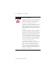
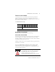
POINT I/O Address Reserve Module Troubleshoot with the Indicators 1734-ARM Module Status Module Module Status Status Network Status Network Status NODE: NODE: Address Reserve No wiring is required for the Address Reserve Module. 0 4 1 5 2 6 3 7 1734 ARM NC = No connection Indication NC NC NC NC NC NC NC NC 41974 Probable Cause Module Status Off No power applied to device. Green Device operating normally.
POINT I/O Address Reserve Module Indication 11 Probable Cause Network Status Off Device is not on line. - Device has not completed dup_MAC_id test. - Device not powered - check module status indicator. Flashing Green Device is on line but has no connections in the established state. Green Device on line and has connections in the established state. Flashing Red One or more I/O connections in timed-out state. Red Critical link failure - failed communication device.
POINT I/O Address Reserve Module Safety Approvals North American Hazardous Location Approval The following information applies when operating this equipment in hazardous locations: Informations sur l’utilisation de cet équipement en environnements dangereux: Products marked “CL I, DIV 2, GP A, B, C, D” are suitable for use in Class I Division 2 Groups A, B, C, D, Hazardous Locations and nonhazardous locations only.
POINT I/O Address Reserve Module 13 Specifications - 1734-ARM Address Reserve Module Module Location 1734-TB or -TBS wiring base assembly Indicators 1 green/red network status indicator, logic side 1 green/red module status indicator, logic side Keyswitch Position Use the keyswitch position of the removed module Pointbus Current 75 mA maximum @ 5V dc Power Dissipation 0.375 W maximum @ 5V dc Thermal Dissipation Dimensions 1.3 BTU/hr maximum @ 5V dc Imperial (Metric) 2.2H x 0.47W x 2.97L in.
POINT I/O Address Reserve Module Certifications (when product C-UL-US - UL Listed for Class I, Division 2, Groups A, B, C and D Hazardous locations, certified is marked)1 for US and Canada CE - CE - C-Tick - 1 European Union 89/336/EEC EMC Directive, compliant with: EN 61000-6-4; Industrial Emissions EN 50082-2; Industrial Immunity EN 61326; Meas./Control/Lab.
POINT I/O Address Reserve Module 15 Publication 1734-IN019A-EN-E - May 2005
Publication 1734-IN019A-EN-E - May 2005 PN 957928-25 © (2005) Rockwell Automation, Inc.