
Instruction Manual


Publication 1734-UM005B-EN-P - June 2001
A-2 Specifications
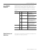
General Specifications
Indicators 3 red/green status indicators
Adapter status
PROFIBUS status
PointBus status
2 green power supply status indicators:
System Power (PointBus 5V power)
Field Power (24V from field supply)
Power Consumption 8.1W maximum @ 28.8V dc
Power Dissipation 2.8W maximum @ 28.8V
Thermal Dissipation 9.5 BTU/hr maximum @ 28.8V dc
Isolation Voltage 1250V rms/V ac
Field Power Bus
Nominal Voltage
Supply Voltage Range
Supply Current
24V dc
10-28.8V dc range,
10A maximum
Dimensions Inches
(Millimeters)
3.0H x 2.16W x 5.25L
(76.2H x 54.9W x 133.4L)
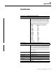
Environmental Conditions
Operational Temperature
Storage Temperature
Relative Humidity
Shock Operating
Non-operating
Vibration
-10 to 55
o
C (14 to 131°F)
-40 to 85
o
C (-40 to 185°F)
5 to 95% noncondensing
30g peak acceleration, 11(±1)ms pulse width
50g peak acceleration, 11(±1)ms pulse width
Tested 5g @ 10-500Hz per IEC 68-2-6
Conductors Wire Size
Category
14 AWG (2.5mm
2
) - 22 AWG (0.25mm
2
) solid or stranded copper
wire rated @ 75°C or higher
3/64 inch (1.2mm) insulation maximum
2
1
Terminal Base Screw Torque 7 pound-inches (0.6Nm)
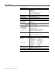
Field Wiring Terminations
PROFIBUS 1 - Not connected 6 - +5V Bus
2 - Not connected 7 - Not connected
3 - +RTX/TX data line 8 - Negative RTX/TX
4 - Request to send 9 - Not connected
5 - Ground Bus Housing - Earth ground
Power Supply 0 - No Connection 1 - No Connection
2 - Chassis Ground 3 - Chassis Ground
4 - Common 5 - Common
6 - Supply 7 - Supply
Mass 9.0 oz/255 grams
Agency Certification (when
product is marked)
CE marked for all applicable directives
C-Tick marked for all applicable acts
1
Use this conductor category information for planning conductor routing as described in publication 1770-4.1, “Industrial
Automation Wiring and Grounding Guidelines.”