
Instruction Manual

Publication 1734-UM005B-EN-P - June 2001
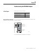
5-4 Grouped Mode
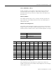
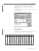
Configuration table and memory map
Note the following module groups:
• slots 1, 2, 3 and 4 - A group of modules with configuration data
• Slots 7, 8 and 9 - A group of modules with configuration data
• Slots 5 and 6 - A group of empty slots
• Slots 12 and 13 - A group of modules without configuration data
(default configuration data)
In this example, the input/output addresses start at byte 0.
Chapter Summary and
What’s Next
In this chapter, you learned how to group modules for reduced
memory space. Move to chapter 6 for information on troubleshooting
your adapter.
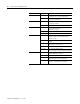
Slot Module
I/O Address
Notes
Input Output
1 1734-OB2E 0.0 to 0.1
2 1734-OB2E/grouped 0.2 to 0.3 Same configuration data as first
module in group (slot 1).
3 1734-OB2E/grouped 0.4 to 0.5
4 1734-OB2E/grouped 0.6 to 0.7
5 1734-OB4E/empty slot 1.0 to 1.3
6 1734-OB4E/grouped empty slot 1.4 to 1.7
7 1734-IB2E 0.0 to 0.1
8 1734-IB2E/grouped 0.2 to 0.3 Same configuration data as first
module in group (slot 7).
9 1734-IV2E/grouped 0.4 to 0.5
10 1734-OE2C 2 to 5
11 1734-IE2C 1 to 4
12 1734-IB4/no configuration 5.0 to 5.3 Default configuration data
13 1734-IB4/grouped 5.4 to 5.7
14 1734-IB4 6.0 to 6.3