
Instruction Manual


1 Publication 1734-UM005B-EN-P - June 2001
Chapter
4
Communication and I/O Table Mapping
This chapter describes the communication process and I/O image
table mapping as they occur through the 1734-APB adapter.
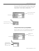
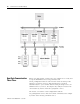
Image Table Mapping
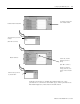
The adapter must map the data it receives to its internal memory
before passing it to the appropriate module. The image table map for
a module is divided into:
• Read bytes - input and status bytes
• Write bytes - output and configuration bytes
The length of each module’s read bytes and write bytes vary in size
depending on module complexity. The following illustration shows
how the adapter maps information. Refer to appendix B for the data
maps of the different POINT I/O modules.
For more information about: See page:
Image Table Mapping 4-1
How Data Communication Takes Place 4-2
Grouping Modules for Memory Management 4-16
Chapter Summary and What’s Next 4-16