
Instruction Manual


Publication 1734-UM005B-EN-P - June 2001
Installing the PROFIBUS Adapter 2-9
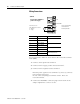
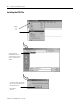
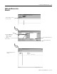
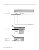
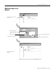
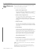
PROFIBUS Connection Plug Wiring
Chapter Summary and
What’s Next
In this chapter, you learned how to install and wire your adapter.
Move to chapter 3 for information on configuring the POINT I/O
system.
Pin Number Name Description
Housing Shield Connected to Chassis Ground
1 Not connected
2 Not connected
3 RX/TX Data + Positive RX/TX data line
4 RTS Request to send
5 Data Ground Isolated ground
6 +5V BUS Isolated +5V from RS485 side
7 Not connected
8 RX/TX Data - Negative RX/TX data line
9 Not connected
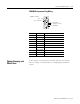
PROFIBUS connection
Pin 3 - RX/TX Data +
Pin 8 - RX/TX Data -
Pin 6 - +5V
Pin 4 - Request to send (R
T
Pin 5 - Data Ground