
Instruction Manual


Publication 1734-UM005B-EN-P - June 2001
2-8 Installing the PROFIBUS Adapter
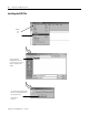
Wiring Connections
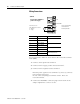
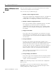
Proceed as follows. Make all connections to the removable terminal
block (RTB).
1. Connect chassis ground to terminal 2.
2. Connect 12/24V supply positive lead to terminal 6.
3. Connect 12/24V negative lead to terminal 4.
External power applied across terminal 6 (+) and 5 (-) connects
to the internal power bus.
Do not connect anything to terminals 0 and 1. These are
reserved terminals.
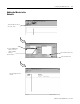
4. Connect the PROFIBUS connector plug to the D-shell on the
adapter. Tighten the screws to secure.
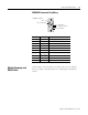
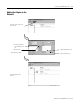
Terminal Description Notes
0 No connection Reserved
1 No connection
2 Chassis Ground
3 Chassis Ground
4 Common
5 Common
6 Voltage Input Apply 12/24V dc. Connects to
the internal power bus.
7 Voltage Input
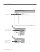
CHAS GND
NC
NC
C
V
CHAS GND
V dc
C
V
0
2
4
6
1
3
5
7
This dc supply will be
connected to the
internal power bus.
12/24V dc
Do not connect 120/240V ac
power to this supply.
NC = No Connection
CHAS GND = Chassis Ground
C = Common
V = Supply