Installation Instructions POINT I/O 2 Port Ethernet Adapter Catalog Number 1734-AENTR Topic Page Important User Information 2 Environment and Enclosure 3 Prevent Electrostatic Discharge 4 About the Adapter 8 Before You Begin 9 Determine Compatibility 9 Understand Messaging 9 Establish I/O Connections 9 Configure Autobaud 10 Install the Adapter 10 Set the Network Address 11 Replace the Adapter 12 Wire the Adapter 14 About the Status Indicators 16 Specifications 20 Additional
POINT I/O 2 Port Ethernet Adapter Important User Information Solid state equipment has operational characteristics differing from those of electromechanical equipment. Safety Guidelines for the Application, Installation and Maintenance of Solid State Controls (Publication SGI-1.1 available from your local Rockwell Automation sales office or online at http://literature.rockwellautomation.com) describes some important differences between solid state equipment and hard-wired electromechanical devices.
POINT I/O 2 Port Ethernet Adapter 3 Environment and Enclosure ATTENTION This equipment is intended for use in a Pollution Degree 2 industrial environment, in overvoltage Category II applications (as defined in IEC 60664-1), at altitudes up to 2000 m (6562 ft) without derating. This equipment is considered Group 1, Class A industrial equipment according to IEC/CISPR 11.
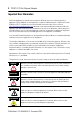
POINT I/O 2 Port Ethernet Adapter Prevent Electrostatic Discharge ATTENTION ATTENTION This equipment is sensitive to electrostatic discharge, which can cause internal damage and affect normal operation. Follow these guidelines when you handle this equipment. • Touch a grounded object to discharge potential static. • Wear an approved grounding wriststrap. • Do not touch connectors or pins on component boards. • Do not touch circuit components inside the equipment.
POINT I/O 2 Port Ethernet Adapter 5 WARNING WARNING WARNING When you connect or disconnect the Removable Terminal Block (RTB) with field side power applied, an electrical arc can occur. This could cause an explosion in hazardous location installations. Be sure that power is removed or the area is nonhazardous before proceeding. If you connect or disconnect the communications cable with power applied to this module or any device on the network, an electrical arc can occur.
POINT I/O 2 Port Ethernet Adapter North American Hazardous Location Approval The following information applies when operating this equipment in hazardous locations: Informations sur l’utilisation de cet équipement en environnements dangereux : Products marked “CL I, DIV 2, GP A, B, C, D” are suitable for use in Class I Division 2 Groups A, B, C, D, Hazardous Locations and nonhazardous locations only.
POINT I/O 2 Port Ethernet Adapter 7 European Hazardous Location Approval European Zone 2 Certification (The following applies when the product bears the Ex Marking) This equipment is intended for use in potentially explosive atmospheres as defined by European Union Directive 94/9/EC and has been found to comply with the Essential Health and Safety Requirements relating to the design and construction of Category 3 equipment intended for use in potentially explosive atmospheres, given in Annex II to this Dir
POINT I/O 2 Port Ethernet Adapter About the Adapter Read this publication for information about the POINT I/O Ethernet adapter, a communications adapter for POINT I/O modules. This adapter is for the POINT I/O backplane that provides connectivity to an Ethernet network with two RJ-45 connectors for 2 port pass-through to support daisy chain or ring, and the existing star and tree network topologies.
POINT I/O 2 Port Ethernet Adapter 9 Before You Begin To effectively use your adapter, note the following considerations. Determine Compatibility RSLogix 5000 version 17 or greater must be used for the 1734-AENTR Add-on Profile. The 1734-AENTR adapters will accept I/O connections with the electronic keying for the 1734-AENT. This allows the 1734-AENTR adapter to be used in a daisy-chain topology with the 1734-AENT profile used for the 1734-AENTR.
POINT I/O 2 Port Ethernet Adapter Configure Autobaud The adapter cannot reconfigure an I/O module that you previously configured to operate at a fixed baud rate. When you reuse a POINT I/O module from another POINT I/O system, configure the module to autobaud before using it with the adapter. Install the Adapter Follow this procedure to install the adapter on the DIN rail prior to installing other base units. ATTENTION Allow 25.4 mm (1 in.) of space between adjacent equipment for adequate ventilation.
POINT I/O 2 Port Ethernet Adapter 11 Set the Network Address The thumbwheel switches are set to 999 and DHCP enabled, by default. You can set the network Internet Protocol (IP) address in the following ways: • Use the thumbwheel switches on the module. • Use a Dynamic Host Configuration Protocol (DHCP) server, such as Rockwell Automation BootP/DHCP. • Retrieve the IP address from nonvolatile memory. The adapter reads the thumbwheel switches first to determine if the switches are set to a valid number.
POINT I/O 2 Port Ethernet Adapter DHCP Enabled and Not Enabled If DHCP is Then the Adapter Enabled Asks for an address from a DHCP server. The DHCP server also assigns other Transport Control Protocol (TCP) parameters Not enabled Uses the IP address (along with other TCP configurable parameters) stored in nonvolatile memory Refer to publication POINT I/O Ethernet Adapter User Manual, 1734-UM014, for more information.
POINT I/O 2 Port Ethernet Adapter 13 6. Slide the safety end cap up to remove it, which exposes the backplane and power connections. ATTENTION Do not discard the end cap. Use this end cap to cover the exposed interconnections on the last mounting base on the DIN rail. Failure to do so could result in equipment damage or injury from electric shock. 7. Position the replacement adapter vertically above the DIN rail, making certain the DIN rail lock is in the horizontal position. 8.
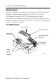
POINT I/O 2 Port Ethernet Adapter Wire the Adapter See the 1734-AENTR Adapter figure for information about how to wire the adapter. ATTENTION Do not wire more than two conductors on any single terminal.
POINT I/O 2 Port Ethernet Adapter 15 1734-AENTR Adapter Node address thumbwheels 002 1734-AENTR POINT I O Module Status Network Activity Link 1 activity/ status Network Status Point Bus Status Link 1 Activity/ Status System Power Ethernet RJ-45 connectors IP ADDRESS Field Power Module status Network activity Network status PointBus status System power Field power NC Chas Gnd C Link 2 Activity/ Status Link 2 activity/ status V 0 12/24V DC Do not connect 120/240V AC power to this supply.
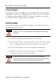
POINT I/O 2 Port Ethernet Adapter About the Status Indicators See Interpret the Status Indicators for information about troubleshooting with the status indicators.
POINT I/O 2 Port Ethernet Adapter 17 Interpret the Status Indicators Indicator State Module status Off No power applied to device Solid green Device operating normally Flashing red/green Module self-test Flashing red Recoverable fault. Complete firmware update, verify address switches. Solid red Unrecoverable fault, may require device replacement Off Device is not on-line - Device has not completed dup_MAC_id test.
POINT I/O 2 Port Ethernet Adapter Indicator State Description Network Activity Off No link established with Port 1 or Port 2. Solid green Link established with Port 1 and/or Port 2 @ 100 Mb. Link established with Port 1 and Port 2. One port @ 100 Mb and the other port @ 10 Mb. Flashing green Transmit or receive activity present on Port 1 and/or Port 2 @ 100 Mb. Transmit or receive activity present on Port 1 and/or Port 2. One port @ 100 Mb and the other port @ 10 Mb.
POINT I/O 2 Port Ethernet Adapter 19 Indicator State Description POINTBus status Off Device is not online. Device has not completed Dup_MAC_ID test. Device not powered - check module status indicator. Flashing green Device is online but has no connections in the established state. Firmware (NVS) update in progress. Solid green Adapter online with connections established.
POINT I/O 2 Port Ethernet Adapter Specifications POINT I/O Ethernet Adapter - 1734-AENTR Attribute Expansion I/O capacity Value • 63 modules max • 5 rack optimized connections (for digital modules only) max • 20 direct connections max • 1734-AENTR backplane current output = 0.8 A. • Actual number of modules can vary. • Add up current requirements of modules you want to use to make sure they do not exceed the amperage limit of 0.8 A for the 1734-AENTR adapter.
POINT I/O 2 Port Ethernet Adapter 21 Power Supply Attribute Value Input voltage rating 24V DC nom 10…28.8V DC range Field side power requirements 24V DC @ 400 mA nom 12V DC @ 800 mA nom 10…28.8V DC, 1000 mA max Inrush current 6 A max for 10 ms Input overvoltage protection Reverse polarity protected PointBus output current 0.
POINT I/O 2 Port Ethernet Adapter General Attribute Value Indicators 3 red/green status indicators on CPU: - Module status - Network status (Ports 1 and 2 combined) - PointBus status 1 green/yellow status indicator on CPU: - Network activity (Ports 1 and 2 combined) 2 green/yellow status indicators on base: - Link 1 activity/status - Link 2 activity/status 2 green power supply status indicators on DC-DC Converter: - System power (5V DC to PointBus Out) - Field power (24V DC from Field In) Power consu
POINT I/O 2 Port Ethernet Adapter 23 General Attribute Value Weight, approx. 280 g (0.62 lb) Wiring category(1) 1 - on power ports 2 - on communications ports Wire size Power connections: 0.34… 2.1 mm² (22…14 AWG) solid or stranded copper wire rated at 75 °C (167 °F ) or greater, 1.2 mm (3/64 in.) insulation max Ethernet connections: RJ-45 connector according to IEC 60603-7, 2 or 4 pair Category 5e minimum cable according to TIA 568-B.
POINT I/O 2 Port Ethernet Adapter Environmental Attribute Value Temperature, operating IEC 60068-2-1 (Test Ad, Operating Cold), IEC 60068-2-2 (Test Bd, Operating Dry Heat), IEC 60068-2-14 (Test Nb, Operating Thermal Shock): -20…55 °C (-4…131 °F) Temperature, storage IEC 60068-2-1 (Test Ab, Unpackaged Non-operating Cold), IEC 60068-2-2 (Test Bb, Unpackaged Non-operating Dry Heat), IEC 60068-2-14 (Test Na, Unpackaged Non-operating Thermal Shock): -40…85 °C (-40…185 °F) Relative humidity IEC 60068-2-
POINT I/O 2 Port Ethernet Adapter 25 Environmental Attribute Value Surge transient immunity IEC 61000-4-5: ±1 kV line-line(DM) and ±2 kV line-earth(CM) on power ports ±2 kV line-earth(CM) on communications ports Conducted RF immunity IEC 61000-4-6: 10V rms with 1 kHz sine-wave 80% AM from 150 kHz…80 MHz Certifications Certification (when Value product is marked)(1) c-UL-us UL Listed Industrial Control Equipment, certified for US and Canada. See UL File E65584.
POINT I/O 2 Port Ethernet Adapter Additional Resources Refer to these related publications, as needed. Resource Description POINT I/O Ethernet User Manual, publication 1734-UM014 Provides details about how to install, configure, and troubleshoot your module You can view or download publications at http://www.literature.rockwellautomation.com. To order paper copies of technical documentation, contact your local Rockwell Automation distributor or sales representative.
POINT I/O 2 Port Ethernet Adapter 27 Notes: Publication 1734-IN040B-EN-P - December 2009
Rockwell Automation Support Rockwell Automation provides technical information on the Web to assist you in using its products. At http://support.rockwellautomation.com, you can find technical manuals, a knowledge base of FAQs, technical and application notes, sample code and links to software service packs, and a MySupport feature that you can customize to make the best use of these tools.