
User Manual Owner manual


Rockwell Automation Publication 1734-UM018B-EN-P - October 2013 69
Configure the Adapter for Direct Connection and Rack Optimization in RSLogix 5000 Software Chapter 5
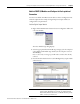
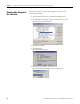
10. Click OK.
At this point, your POINTBus status LED should be solid green. All the
yellow triangles in your I/O configuration should be gone.
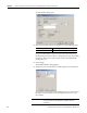
11. Click OK to close the dialog.
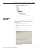
12. Click File → Save to save the project.
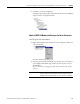
Access Module Data
Use the following information to use the I/O adapter data in the ladder logic
program:
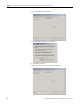
• POINT_IO_Adapter — the name you gave to your EtherNet adapter
• # — slot number of POINT I/O module
• C — configuration, I = input, O = output
Use the controller tags in your ladder program to read input data or write output
data.
• For ControlLogix controller information, refer to ControlLogix System
User Manual, publication 1756-UM001
.
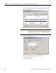
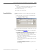
• Slot Status Bits: The Slot Status bits display the connection status for each
of the POINT I/O modules that use a rack-optimized connection.
– Bit 0 is reserved for the adapter and always reports a value of 1.
– Each of the other bits (1 to 63) correspond to a POINT I/O module
that you install in the POINT I/O backplane.
– In this example, we configured the 1734-AENT adapter for both rack-
optimized and direct connections.
The slot status bits indicate that we installed the module in slot 2 with it
operating correctly:
0 = module participating with no errors and
1 = module not participating or connection error (typically, module
removed/missing)