User Manual 1734 POINT I/O EtherNet/IP Adapters Catalog Number 1734-AENT, Series B
Important User Information Solid-state equipment has operational characteristics differing from those of electromechanical equipment. Safety Guidelines for the Application, Installation and Maintenance of Solid State Controls (publication SGI-1.1 available from your local Rockwell Automation sales office or online at http://www.rockwellautomation.com/literature/) describes some important differences between solid-state equipment and hard-wired electromechanical devices.
Preface Read this preface to familiarize yourself with the rest of the manual. It provides information concerning: • who should use this manual • the purpose of this manual • related documentation • conventions used in this manual Who Should Use this Manual Use this manual if you are responsible for designing, installing, programming, or troubleshooting control systems that use Series B 1734 POINT I/O™ EtherNet/IP Adapter modules.
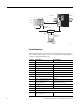
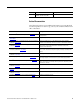
1734-AENT 10.88.70.2 0 0 2 1734-AENT Series B POINT I O Module Status Network Activity POINT I/O Network Status Slot 0 1 2 3 Point Bus Status System Power Field Power Local chassis IP ADDRESS Data 1756-ENBT 10.88.70.4 (slot 3) L63 controller (slot 1) Slot 0 1 2 3 4 Switch 10.88.70.26 Programming terminal 31393 System Components We used the following components for the example applications.
Quantity 1 Product Name Catalog Number RSLogix 5000 programming software, version 17 or later 9324-RLD300ENE Related Documentation The following documents contain additional information concerning Rockwell Automation products. To obtain a copy, contact your local Rockwell Automation office or distributor. Resource Description 1734 POINT I/O® Selection Guide, publication 1734-SG001 A description and overview of the 1734 series I/O modules and compatible control platforms.
Common Techniques Used in this Manual The following conventions are used throughout this manual: • Bulleted lists such as this one provide information, not procedural steps. • Numbered lists provide sequential steps or hierarchical information. • Italic type is used for emphasis. Rockwell Software products contain extensive tutorials and help screens. We recommend that you use these tutorials and help screens to learn about the products.
Table of Contents Preface Who Should Use this Manual . . . . . . . . . . . . . . . . . . . . . . . . . . . . . . . . . . . . . . . i Purpose of this Manual . . . . . . . . . . . . . . . . . . . . . . . . . . . . . . . . . . . . . . . . . . . . . i About the Example Applications. . . . . . . . . . . . . . . . . . . . . . . . . . . . . . . . . i System Components. . . . . . . . . . . . . . . . . . . . . . . . . . . . . . . . . . . . . . . . . . . ii Related Documentation. . . . . . . . . . . . . . . . . . . .
Table of Contents Chapter 3 Configure the Adapter with RSLogix5000 software Introduction . . . . . . . . . . . . . . . . . . . . . . . . . . . . . . . . . . . . . . . . . . . . . . . . . . . . . Configuration Requirements . . . . . . . . . . . . . . . . . . . . . . . . . . . . . . . . . . . . . . IP Address . . . . . . . . . . . . . . . . . . . . . . . . . . . . . . . . . . . . . . . . . . . . . . . . . . . Gateway Address . . . . . . . . . . . . . . . . . . . . . . . . . . . . . . . . . . . . . . . . . .
Table of Contents Verify the Module Chassis Size . . . . . . . . . . . . . . . . . . . . . . . . . . . . . . . . . . . . 65 Access Module Data . . . . . . . . . . . . . . . . . . . . . . . . . . . . . . . . . . . . . . . . . . . . . . 68 Chapter Summary. . . . . . . . . . . . . . . . . . . . . . . . . . . . . . . . . . . . . . . . . . . . . . . . 68 Chapter 6 Troubleshoot the Adapter Interpret the Status Indicators. . . . . . . . . . . . . . . . . . . . . . . . . . . . . . . . . . . . .
Table of Contents viii Rockwell Automation Publication 1734-UM018B-EN-P - October 2013
Chapter 1 Overview of the 1734 POINT I/O EtherNet/IP Adapter Overview This chapter provides an overview of the POINT I/O® Series B EtherNet/IP adapter, its primary features, and how to use it. You need to understand the concepts discussed in this chapter to configure your adapter and use it in an EtherNet/IP control system. The following table lists where to find specific information.
Chapter 1 Overview of the 1734 POINT I/O EtherNet/IP Adapter Some of the module’s features are as follows: • EtherNet/IP messages encapsulated within standard TCP/UDP/IP protocol • Common application layer with ControlNet and DeviceNet networks • Interfacing via Category 5 rated twisted pair cable • Half/full duplex 10 Mbit or 100 Mbit operation • DIN rail mounting • Communication to and from other POINT I/O modules on the same DIN rail • Communication supported by RSLinx software • IP address assigned vi
Overview of the 1734 POINT I/O EtherNet/IP Adapter Physical Features of Your Adapter Chapter 1 The 1734 Adapters have the following components: • Removable Terminal Block (RTB); • Network address Thumbwheel • Connector (one RJ45 EtherNet/IP connector) • Status indicators (Module Status; Network Status; POINTBus Status; Network Activity; Link 1 Activity/Status; Link 2 Activity/Status; System Power; Field Power) Physical Features of the 1734-AENT Series B Adapters Status indicators RTB removal handle sB
Chapter 1 Overview of the 1734 POINT I/O EtherNet/IP Adapter Important Adapter Considerations Before you begin using your adapter, note the following important considerations. ATTENTION: You must only use Series C and above POINT I/O modules with 1734-AENT EtherNet/IP Adapters. Series A or Series B POINT I/O modules do not work with 1734-AENT EtherNet/IP Adapters (does not apply to POINTGuard modules).
Overview of the 1734 POINT I/O EtherNet/IP Adapter Chapter 1 Adapter Replacement Note that during a connection request from the controller, the chassis size setting is not communicated to the adapter. You must always set this chassis size using a separate operation. This includes situations when you are replacing an adapter. The adapter does not allow any I/O connections until it is configured with the appropriate chassis size and the proper number of POINT I/O modules are present.
Chapter 1 Overview of the 1734 POINT I/O EtherNet/IP Adapter • If modules of different types are removed and returned to the wrong locations, attempts to connect to these modules will fail during verification of the electronic ID (providing that keying has not been disabled). • If modules of the same type are removed and returned to the wrong locations, they accept connections from the controller or controllers and reconfigure with the correct data once they pass their electronic keying check.
Overview of the 1734 POINT I/O EtherNet/IP Adapter Understand the Producer/ Consumer Model Chapter 1 The CIP producer and consumer networking model replaces the old source and destination (master and slave) model. The producer and consumer model reduces network traffic and increases speed of transmission. In traditional I/O systems, controllers poll input modules to obtain their input status. In the CIP system, input modules are not polled by a controller.
Chapter 1 Overview of the 1734 POINT I/O EtherNet/IP Adapter Rack-optimized connections reduce the total number of connections needed to transfer data when using many digital I/O modules in a system. The following example illustrates the benefit of rack-optimized connections. Assume you set up a system that contains eight digital I/O modules interfaced to an adapter.
Overview of the 1734 POINT I/O EtherNet/IP Adapter Chapter 1 Understand Messaging Class 3 (Explicit Message) requests through the 1734-AENT adapter to a specific POINT I/O module may not always receive a response from the I/O modules. In the case where the I/O module does not reply to the request, the adapter responds with an error code indicating a timeout. Configure Autobaud The adapter cannot reconfigure an I/O module that you previously configured to operate at a fixed communication rate.
Chapter 1 Overview of the 1734 POINT I/O EtherNet/IP Adapter Notes: 10 Rockwell Automation Publication 1734-UM018B-EN-P - October 2013
Chapter 2 Install Your 1734 POINT I/O EtherNet/IP Adapter Overview This chapter describes how to physically install the POINT I/O Series B EtherNet/IP adapter; and how to connect the adapter to your EtherNet/IP network. The only tools you require are a flat or Phillips head screwdriver and a drill.
Chapter 2 Install Your 1734 POINT I/O EtherNet/IP Adapter Mount the POINT I/O Adapter on a DIN Rail 1. Make sure the DIN rail locking screw (orange) is in horizontal position. 2. Position the adapter vertically above an IEC standard (35 x 7.5 x 1 mm) top-hat DIN rail at a slight angle (DIN rail: Allen-Bradley part number 199-DR1; 46277-3). 3. Press down firmly to install the adapter on the DIN rail, noting that the locking mechanism locks the adapter to the DIN rail. ATTENTION: Allow 25.4 mm (1.0 in.
Install Your 1734 POINT I/O EtherNet/IP Adapter Chapter 2 Install POINT I/O Modules The following instructions explain how to install your POINT I/O Modules onto the DIN rail. 1. Position the mounting base vertically above the DIN rail. 2. Make certain the adapter DIN rail locking screw (orange) is in the horizontal position. 3. Slide the I/O module mounting base down, allowing the interlocking side pieces to engage the adjacent mounting base/adapter. 4.
Chapter 2 Install Your 1734 POINT I/O EtherNet/IP Adapter Replace An Adapter Use these procedures to install a replacement POINT I/O adapter to an existing system. 1. Disconnect the Ethernet connector(s) from the adapter. 2. Pull up on the Removable Terminal Block (RTB) handle to remove the terminal block. 3. Remove the adjacent module from its mounting base. 4. Use a small bladed screwdriver to rotate the DIN rail locking screw (orange) to a vertical position. This releases the locking mechanism. 5.
Install Your 1734 POINT I/O EtherNet/IP Adapter Wire the Adapter Chapter 2 The POINT I/O adapter uses RJ45 EtherNet/IP connectors for its EtherNet/ IP connection. Connect the cord set you selected for your module to the appropriate port. Wire a POINT I/O Adapter Refer to the following illustration to wire the adapter. Network address thumbwheels 0 0 2 RJ45 EtherNet/IP Connector NC Chas C V 43264 0 1 NC NC Chas Gnd Chas Gnd 2 3 4 This DC supply connects to the internal power bus.
Chapter 2 Install Your 1734 POINT I/O EtherNet/IP Adapter ATTENTION: Do not wire more than two conductors on any single terminal. WARNING: When you connect or disconnect the Removable Terminal Block (RTB) with field side power applied, an electrical arc can occur. This could cause an explosion in hazardous location installations. Be sure that power is removed or the area is nonhazardous before proceeding.
Chapter 3 Configure the Adapter with RSLogix5000 software Introduction This chapter guides you through the steps required to configure your modules using the RSLogix 5000 software. Note that the modules presented in this chapter can be configured using RSLogix 5000 software, version 17, or later. Before using your adapter in an EtherNet/IP network, you need to configure it with an IP address, subnet mask, and optional Gateway address.
Chapter 3 Configure the Adapter with RSLogix5000 software Configuration Requirements Before you can use your adapter, you must configure its IP address, its subnet mask, and, optionally, a gateway address. You can use the Rockwell BootP utility, version 2.3 or later, to perform the configuration. You can also use a DHCP server or the network address switches to configure these parameters. ATTENTION: You must only use Series C and above POINT I/O modules with 1734-AENT EtherNet/IP Adapters.
Configure the Adapter with RSLogix5000 software Chapter 3 If using the BootP/DHCP utility, you need to know the Ethernet hardware address of your adapter. Rockwell Automation assigns each 1734-AENT adapter a unique 48-bit hardware address at the factory. The address is printed on a label on the side of your 1734-AENT adapter as shown in the figure. It consists of six hexadecimal digits separated by colons. This address is fixed by the hardware and cannot be changed.
Chapter 3 Configure the Adapter with RSLogix5000 software Gateway Address This section applies to multi-network systems. If you have a single network system, refer to the next section. The Gateway Address is the default address of a network. It provides a single domain name and point of entry to the site. Gateways connect individual physical networks into a system of networks. When a node needs to communicate with a node on another network, a gateway transfers the data between the two networks.
Configure the Adapter with RSLogix5000 software Chapter 3 Subnet Mask The subnet mask is used for splitting IP networks into a series of subgroups, or subnets. The mask is a binary pattern that is matched up with the IP address to turn part of the Host ID address field into a field for subnets. EXAMPLE Take Network 2 (a Class B network) in the previous example and add another physical network.
Chapter 3 Configure the Adapter with RSLogix5000 software Set the Network Address The adapters ship DHCP-enabled and with the Network address thumbwheel switches set to 999. You can set the network Internet Protocol (IP) address as follows. Set the Network Address for POINT I/O Adapters • Use the thumbwheel switches located on the adapter. Press either the + or buttons to change the number and assign the IP address.
Configure the Adapter with RSLogix5000 software Chapter 3 If DHCP is not enabled, the adapter uses the IP address, along with other TCP configurable parameters, stored in non-volatile memory. WARNING: When you change switch settings while power is on, an electrical arc can occur. This could cause an explosion in hazardous location installations. Be sure that power is removed or the area is nonhazardous before proceeding.
Chapter 3 Configure the Adapter with RSLogix5000 software 3. Double-click the hardware address of the device you want to configure. The New Entry dialog appears with the device’s Ethernet Address (MAC). 4. Enter the IP Address you want to assign to the device and click OK. The device is added to the Relation List, displaying the Ethernet Address (MAC) and corresponding IP Address, Hostname, and Description (if applicable).
Configure the Adapter with RSLogix5000 software Chapter 3 5. When the address displays in the IP Address column in the Request History section, the IP address assignment has been made. 6. To make this configuration static in the device, highlight the device in the Relation List panel, and click the Disable BOOTP/DHCP button. When power is cycled to the device, it uses the configuration saved in nonvolatile memory and will not issue a DHCP request. 7.
Chapter 3 Configure the Adapter with RSLogix5000 software 1. Select Save As... from the File menu. The Save As dialog appears. 2. Select the folder where you want to save the Relation List. 3. Enter a File name for the Relation List, for example, control system configuration, and click Save. You can leave the Save as type at the default setting: Bootp Config Files (*.bpc). You now have the option to open the file containing the Relation List at a later session.
Configure the Adapter with RSLogix5000 software Use DHCP Software to Configure Your Adapter Chapter 3 DHCP (Dynamic Host Configuration Protocol) software automatically assigns IP addresses to client stations logging onto a TCP/IP network. DHCP is based on BootP and maintains some backward compatibility. The main difference is that BootP was designed for manual configuration, while DHCP allows for dynamic allocation of network addresses and configurations to newly attached devices.
Chapter 3 Configure the Adapter with RSLogix5000 software Notes: 28 Rockwell Automation Publication 1734-UM018B-EN-E - October 2013
Chapter 4 Configure the Adapter for Direct Connection in RSLogix 5000 Software Overview In this example, a ControlLogix controller communicates with I/O modules via the adapter using a direct connection. The adapter makes a direct connection to each of the modules referenced by the data. The modules presented in this chapter use RSLogix 5000 software, revision 17 and above.
Chapter 4 Configure the Adapter for Direct Connection in RSLogix 5000 Software Set Up the Hardware In this example, a ControlLogix chassis contains the L63 controller in slot 1 and a 1756-ENBT bridge module in slot 3. The 1734-AENT adapter is mounted on a DIN rail in slot 0, with a 1734-OW2/C relay output module in slot 1, a 1734OV4E/C sink output module in slot 2, and a power supply (not shown). To work along with this example, set up your system as shown in the figure. 1734-AENT 10.88.70.
Configure the Adapter for Direct Connection in RSLogix 5000 Software Create the Example Application Chapter 4 Perform the following steps to create the example application: 1. Start RSLogix 5000 Enterprise Series software to open the RSLogix 5000 main dialog. 2. From the File menu, select New. 3. The New Controller dialog opens. 4. Enter an appropriate Name for the Controller, for example, POINT_IO_Controller.
Chapter 4 Configure the Adapter for Direct Connection in RSLogix 5000 Software 5. Select the correct Version, Chassis Type, and Slot number of the L63 controller, and the folder where you want to save the RSLogix 5000 file (Create In). The Description is optional. 6. Click OK. Configure the I/O Modules You now add the POINT I/O modules to the controller’s I/O configuration performing these procedures: • Add the local 1756-ENBT Bridge module to the I/O configuration.
Configure the Adapter for Direct Connection in RSLogix 5000 Software Chapter 4 2. The Select Module Type dialog opens. 3. Select the appropriate Module Type filter Category (for the example we selected Communication), and Module Type Vendor (for the example we selected Allen-Bradley).
Chapter 4 Configure the Adapter for Direct Connection in RSLogix 5000 Software 6. Enter values for Name, IP Address, and Slot, noting that we used the following values: Name IP Address Slot Local_ENBT 10.88.70.4 3 Note the module definition properties on the bottom left of the New Module dialog. You have the option to change these properties by clicking the Change button. Some of the properties cannot be modified while pending edits exists. To change the default module properties, 7. Click Change...
Configure the Adapter for Direct Connection in RSLogix 5000 Software Add the POINT I/O Adapter to the I/O Configuration Chapter 4 Next, you must add the POINT I/O adapter as a child of the local 1756-ENBT module. 1. In the Project dialog, right-click the local 1756-ENBT module under the I/O Configuration folder, and select New Module from the dialog. The Select Module Type dialog opens. 2.
Chapter 4 Configure the Adapter for Direct Connection in RSLogix 5000 Software 3. Select your adapter from the list and click Create. The New Module dialog opens. 4. Select the General Tab and enter the module details, noting that we used the following values. Name POINT IO Adapter IP Address 10.88.70.2 IMPORTANT Note that the slot field is disabled because the slot is automatically 0 for the 1734-AENT/B adapter. 5. Click Change... The Module Definition dialog opens. 6.
Configure the Adapter for Direct Connection in RSLogix 5000 Software IMPORTANT Chapter 4 The chassis size value equals 1 for the adapter plus the number of I/O modules installed (physically present on the I/O backplane). Connection choices are the following: • None – the adapter only makes a direct connection to each of the modules referenced by the data. RPI is disabled in this case. • Rack optimization – digital I/O data is collected into a rack image.
Chapter 4 Configure the Adapter for Direct Connection in RSLogix 5000 Software Add the POINT I/O Modules to the I/O Configuration You now add POINT I/O modules to the I/O Configuration List under the adapter. TIP ATTENTION: This example application uses I/O module default configurations. For more information, refer to the POINT I/O Selection Guide, publication 1734-SG001. In this example, you add a 1734-OW2 relay output module and a 1734-OV4E sink output module with standard configurations.
Configure the Adapter for Direct Connection in RSLogix 5000 Software Chapter 4 3. From the modules listed select the 1734-OW2 relay output module and click Create. The New Module dialog opens. 4. Enter values for Name and Slot, noting that we used the following values.
Chapter 4 Configure the Adapter for Direct Connection in RSLogix 5000 Software 5. Choose the Connection tab. RPI is selectable since it is a direct connection. Note that the RPI is selectable on the screen and has a default value. Because we are making a direct connection to each I/O module, we must specify an RPI to determine how often the data is exchanged with the 1734-AENTR adapter for each module. 6.
Configure the Adapter for Direct Connection in RSLogix 5000 Software Chapter 4 Add the Digital Output Module 1. Highlight the 1734-AENT/B adapter under the I/O Configuration folder, right-click and select New Module.. The Select Module Type dialog opens. 2. Select the appropriate Module Type Category Filter (for the example we selected Digital) and Module Type Vendor (for the example, we selected Allen-Bradley). Note: to select only one category you will need to unselect those already selected. 3.
Chapter 4 Configure the Adapter for Direct Connection in RSLogix 5000 Software 4. Enter values for Name and Slot, noting that we used the following values. Name Slot POINT_Digital_Output 2 5. Choose the Connection tab to set the RPI value. The RPI is selectable since it is a direct connection. 6. Enter 10 ms as the RPI for the 1734-OV4E module to set how often you exchange data with the I/O adapter.
Configure the Adapter for Direct Connection in RSLogix 5000 Software Edit the Controller Tags Chapter 4 When you add modules to the I/O configuration the system creates tags for those modules to use in the application program. For the example application you need to add one more controller tag. 1. Double-click the Controller Tags folder in the project dialog. The Controller Tags dialog opens. You see the tags created for the 1734-AENT adapter and its digital I/O modules.
Chapter 4 Configure the Adapter for Direct Connection in RSLogix 5000 Software Create the Ladder Program Create the example ladder program to test the I/O. 1. Under the Main Program folder, double-click Main Routine. 2. Enter the following ladder program using the tags previously created. 3. Save the program. Download the Program to the Controller Follow this procedure to download the program you just saved to the ControlLogix controller. 1. From the main menu, choose Communications>Who-Active.
Configure the Adapter for Direct Connection in RSLogix 5000 Software Chapter 4 4. Choose Download. The Download dialog opens with a reminder of the following. • The controller is in Remote Run mode. • The mode changes to Remote Program prior to download. 5. From the Download dialog, choose Download The RSLogix 5000 software dialog opens. 6. Notice that the 1756-ENBT Bridge is now online. If yellow triangles are present, see the following section.
Chapter 4 Configure the Adapter for Direct Connection in RSLogix 5000 Software 3. Select Properties. 4. Click the Connection tab. The Module Fault error code displays. 5. Click the Chassis Size tab. 6. Click Set Chassis Size in Module.
Configure the Adapter for Direct Connection in RSLogix 5000 Software Chapter 4 7. Read and acknowledge the warning dialog. 8. Click OK to continue. Notice the chassis size stored in the module has been changed to 3. At this point, your POINTBus status LED should be solid green. All the yellow triangles in your I/O configuration should be gone. 9. Click OK.
Chapter 4 Configure the Adapter for Direct Connection in RSLogix 5000 Software Configure the Adapter with Fixed IP Address To configure the adapter with a fixed IP address to prevent the adapter from ceasing to communicate with the ControlLogix controller: 1. All controllers with I/O connections to the AENT and/or the modules in its backplane need to be in program mode. 2. In the Module Properties dialog, click the Internet Protocol tab. 3. If it is not selected, select Manually configure IP settings.
Configure the Adapter for Direct Connection in RSLogix 5000 Software Recover From an Overloaded Adapter Chapter 4 Each I/O connection established with the I/O adapter consumes a portion of microprocessor bandwidth. The amount of bandwidth used by a connection depends on several variables, such as the requested packet interval (RPI), number of I/O modules involved in the connection, and rate of change of the I/O.
Chapter 4 Configure the Adapter for Direct Connection in RSLogix 5000 Software Chapter Summary 50 This chapter provided instructions on how to configure the POINT I/O Adapter for Direct Connection through the the RSLogix 5000 software. It included information about setting up the hardware and configuring the I/O, adding the adapter to the configuration, and configuring the adapter with a fixed IP address.
Chapter 5 Configure the Adapter for Direct Connection and Rack Optimization in RSLogix 5000 Software Overview This chapter guides you through the steps required to configure your AENT adapter with both direct and rack-optimized I/O connections using RSLogix 5000 software. You can mix I/O connection formats for different I/O modules communicating through the same adapter. I/O modules set up to use rack optimization communicate at the rate of the RPI configured for the adapter.
Chapter 5 Configure the Adapter for Direct Connection and Rack Optimization in RSLogix 5000 Software Set Up the Hardware The following section describe how to set up the I/O Hardware. Set Up the POINT I/O Hardware In this example, a ControlLogix chassis contains the L63 controller in slot 1 and a 1756-ENBT bridge module in slot 3.
Configure the Adapter for Direct Connection and Rack Optimization in RSLogix 5000 Software Create the Example Application Chapter 5 Perform the following steps to create the example application: 1. Start the RSLogix 5000 Enterprise Series software. The RSLogix 5000 software main dialog opens. 2. From the File menu, select New. 3. The New Controller dialog opens. 4. Enter an appropriate Name for the Controller, for example, POINT_IO_Controller. 5.
Chapter 5 Configure the Adapter for Direct Connection and Rack Optimization in RSLogix 5000 Software Configure the I/O Modules You now add the I/O modules to the controller I/O configuration. To do this, first add the local 1756-ENBT Bridge module to the I/O configuration. Next, add the I/O adapter as a child of the 1756-ENBT module, and then add the I/O modules as children of the adapter.
Configure the Adapter for Direct Connection and Rack Optimization in RSLogix 5000 Software Chapter 5 2. Select the appropriate Module Type filter Category (for the example we selected Communication), and Module Type Vendor (for the example we selected Allen-Bradley).
Chapter 5 Configure the Adapter for Direct Connection and Rack Optimization in RSLogix 5000 Software 5. Enter values for Name, IP Address, and Slot, noting that we used the following values: Name IP Address Slot Local_ENBT 10.88.70.4 3 Note the module definition properties on the bottom left of the New Module dialog. You have the option to change these properties by clicking the Change button. Some of the properties cannot be modified while pending edits exists.
Configure the Adapter for Direct Connection and Rack Optimization in RSLogix 5000 Software Add the POINT I/O Adapter to the I/O Configuration Chapter 5 Next, you must add the POINT I/O adapter as a child of the local 1756-ENBT module. 1. In the Project dialog, right-click the local 1756-ENBT module under the I/O Configuration folder, and select New Module from the dialog. The Select Module Type dialog opens. 2.
Chapter 5 Configure the Adapter for Direct Connection and Rack Optimization in RSLogix 5000 Software 3. Select your adapter (in this example, we use 1734-AENT/B) from the list and click Create. The New Module dialog opens. 4. Select the General Tab and enter the module details, noting that we used the following values. Name IP Address IMPORTANT POINT_IO_Adapter 10.88.70.2 Note that the slot field is disabled because the slot is automatically 0 for the 1734-AENT/B adapter. 5. Click Change...
Configure the Adapter for Direct Connection and Rack Optimization in RSLogix 5000 Software Chapter 5 6. Enter or select values for Series, Revision, Electronic Keying, Connection, and Chassis Size, noting that we used the following values: Series Connection Chassis Size Electronic Keying Revision IMPORTANT B Rack Optimization 5 Compatible Module 4.3 The chassis size value equals 1 for the adapter plus the number of I/O modules installed (physically present on the I/O backplane).
Chapter 5 Configure the Adapter for Direct Connection and Rack Optimization in RSLogix 5000 Software 9. In the New Module screen select the Connection Tab. 10. Verify that the Requested Packet Interval (RPI) used for the rackoptimized connection to the I/O modules is appropriate for your system (20.0 ms for this example). If not, change it to the correct value. IMPORTANT To avoid overloading the adapter, it is recommended that the RPI be no less than 10.0 ms for rack connections and 50.
Configure the Adapter for Direct Connection and Rack Optimization in RSLogix 5000 Software Chapter 5 Add the POINT I/O Modules and Configure for Rack-optimized Connection You must now add the ArmorPoint I/O modules to the I/O Configuration List under the adapter. In this example, the digital input and output modules are configured for rack optimization. Add the Digital Output Module 1.
Chapter 5 Configure the Adapter for Direct Connection and Rack Optimization in RSLogix 5000 Software The New Module dialog opens. 4. Enter values for Name and Slot, noting that we used the following values. Name Slot POINT_Relay_Output 1 Note the module definition properties on the bottom left of the New Module dialog. You have the option to change these properties by clicking the Change... button. Some of the properties cannot be modified while pending edits exist. 5. Select Change...
Configure the Adapter for Direct Connection and Rack Optimization in RSLogix 5000 Software Chapter 5 7. Click OK to accept the configuration. The digital input module appears indented under the local 1734-AENT/B adapter in the I/O Configuration folder. Add the POINT I/O Module and Configure For Direct Connection Add The Digital Sink Output Module 1. Right-click the POINT I/O Chassis in the I/O Configuration folder and select New Module. The Select Module Type dialog opens. 2.
Chapter 5 Configure the Adapter for Direct Connection and Rack Optimization in RSLogix 5000 Software 3. From the modules listed select the 1734-OV4E/C Digital Sink Output module and click Create. TIP In the Select Module Type dialog, you have options to search for a specific module, add modules to a Favorites list, filter by Category and/or Vendor, Hide and Show Filters, use Module Discovery, sort by vendor, or access your Favorites list. The New Module dialog opens. 4.
Configure the Adapter for Direct Connection and Rack Optimization in RSLogix 5000 Software Chapter 5 5. Select Change... The Module Definition dialog displays. 6. For Connection, select Data. This configures the controller to make a Direct I/O Connection to the module. 7. Click OK. 8. From the New Module dialog, click the Connection tab. The New Module dialog opens. 9. From the New Module dialog, enter 50 for the Requested Packet Interval (RPI). 10. Keep the following unchecked. a. Inhibit Module b.
Chapter 5 Configure the Adapter for Direct Connection and Rack Optimization in RSLogix 5000 Software Download the Program to the Controller Follow this procedure to download the program we just saved to the ControlLogix controller. 1. From the main menu, choose Communications>Who Active. 2. From the Who Active dialog, navigate to select the slot where the controller is located in the chassis. 3. Click Set Project Path. 4. Click Download. The Download dialog opens. 5.
Configure the Adapter for Direct Connection and Rack Optimization in RSLogix 5000 Software Chapter 5 Notice that the 1756-ENBT Bridge is now online. If yellow triangles are present, see the following section. Verify the Module Chassis Size You have now built the I/O tree and the RSLogix 5000 software uses the chassis size from the General tab of the adapter for the rack-optimized I/O connection. Now you need to configure this new chassis size value into the adapter nonvolatile memory.
Chapter 5 Configure the Adapter for Direct Connection and Rack Optimization in RSLogix 5000 Software 6. Click Set Chassis Size in Module. 7. Read and acknowledge the warning dialog. 8. Click OK to continue. 9. Notice the chassis size in the module is modified to 5.
Configure the Adapter for Direct Connection and Rack Optimization in RSLogix 5000 Software Chapter 5 10. Click OK. At this point, your POINTBus status LED should be solid green. All the yellow triangles in your I/O configuration should be gone. 11. Click OK to close the dialog. 12. Click File →Save to save the project.
Chapter 5 Configure the Adapter for Direct Connection and Rack Optimization in RSLogix 5000 Software Chapter Summary 70 This chapter provided instructions on configuring an AENT Adapter for Direct Connection and Rack Optimization in RSLogix 5000 Software. It included information about hardware setup; configuring the I/O Modules; adding an I/O adapter to the I/O configuration; configuring for rack-optimized connections; configuring for direct connections; and accessing module data.
Chapter 6 Troubleshoot the Adapter This chapter describes the different status indicators available in the 1734 POINT I/O EtherNet/IP adapter and how to interpret these indicators to help troubleshoot the module. The following table lists where to find specific information Topic Page Interpret the Status Indicators 69 Status Indicators for POINT I/O Adapters 70 ATTENTION: You must only use Series C and above POINT I/O modules with 1734-AENT EtherNet/IP Adapters.
Chapter 6 Troubleshoot the Adapter Status Indicators for POINT I/O Adapters The following describes the status indicators on the 1734-AENT. 0 0 2 Module Status Network Activity Network Status POINTBus Status System Power Field Power 43264 Status Indicators for 1734-AENT Adapter Indicator Status Description Module Status Off No power applied to device Flashing green Device needs commissioning due to missing, incomplete, or incorrect configuration. Solid green Device is operating normally.
Troubleshoot the Adapter Chapter 6 Status Indicators for 1734-AENT Adapter Indicator Status Description POINTBus Status Off Device not powered – check module status indicator. Flashing red/green LED cycle power test present. Flashing red Recoverable fault occurred: • At cycle power the number of expected modules does not equal the number of modules present • A module is missing • Node fault (I/O connection timeout) occurred. Solid red Unrecoverable fault occurred – the adapter is bus off.
Chapter 6 Troubleshoot the Adapter Notes: 72 Rockwell Automation Publication 1734-UM018B-EN-P - October 2013
Appendix A Specifications General Specifications The 1734-AENT adapters have the following general specifications. General Specifications Attributes Description Expansion I/O capacity, max •63 modules •5 rack-optimized connections (for digital modules only) •31 direct connections(1) •Backplane current output = 1.0 A. •Actual number of modules can vary. •Add together the current requirements for the modules you want to use to make sure they do not exceed the amperage limit of 1.0 A for the adapter.
Appendix A Specifications General Specifications Attributes Description Status indicators 3 red/green status indicators (on CPU): • – Module status • – Network status • – POINTBus status 1 green status indicator on CPU: • – Network activity 2 green power supply status indicators on DC-DC Converter: • – System power (5V DC to POINTBus Out) • – Field power (24V DC from Field In) Wire Size Power connections: 0.34... 2.1 mm2 (22...
Specifications Appendix A Power Supply Specifications EtherNet Communication Attributes Description Input overvoltage protection Reverse polarity protected POINTBus output, max 5V DC @ 1.0 A Interruption Output voltage stays within specifications when input drops out for 10 ms @ 10V with max load The 1734-AENT adapter modules have the following EtherNet communication specifications.
Appendix A Specifications Environmental Specifications 76 Attributes Description Emissions CISPR 11: Group 1, Class A ESD immunity IEC61000-4-2: 6 kV contact discharges 8 kV air discharges Radiated RF immunity IEC 61000-4-3: 10V/m with 1 kHz sine-wave 80% AM from 30...2000 MHz 10V/m with 200 Hz 50% Pulse 100% AM @ 900 MHz 10V/m with 200 Hz 50% Pulse 100% AM @ 1890 MHz 10V/m with 1 kHz sine-wave 80% AM from 2000...
Specifications Certifications Appendix A The 1734-AENT EtherNet/IP Adapter modules have the following Certifications. Certifications Certification (when product is marked)(1) 1734-AENT, Series B c-UL-us UL Listed Industrial Control Equipment, certified for US and Canada. See UL File E65584. UL Listed for Class I, Division 2 Group A,B,C,D Hazardous Locations, certified for U.S. and Canada. See UL File E194810. CE European Union 2004/108/EC EMC Directive, compliant with: EN 61326-1; Meas./Control/Lab.
Appendix A Specifications Notes: 78 Rockwell Automation Publication 1734-UM018B-EN-P - October 2013
Appendix B Adapter Web Dialogs Overview Work with the Home Page The Web dialog of the I/O adapter offers extensive internal and network diagnostics. To view the Web dialogs, enter the IP address of the I/O adapters into your browser.
Appendix B Adapter Web Dialogs To display and work with the adapter diagnostics home page, follow these procedures. IMPORTANT Make sure that your PC Internet LAN setting and your TCP/IP settings are configured to access the subnet on which your adapter communicates. 1. From your web browser, enter the adapter IP address to see the Home page. Enter the adapter IP address to see the home page. 2.
Adapter Web Dialogs Appendix B – Allen-Bradley logo at the top of the page – Visit ab.com for additional information statement under Resources • Click Rockwell Automation at the top right to go to www.rockwellautomation.com. • Click the following to see additional diagnostics web pages.
Appendix B Adapter Web Dialogs Use the Diagnostic Overview Page To use the Diagnostic Overview page for general diagnostics information, follow this procedure. 1. Click Diagnostic Overview from the tab at the top of the page or panel on the left. The Diagnostic Overview page opens. Download EDS files for your adapter 2.
Adapter Web Dialogs Appendix B – Current CIP I/O Connections – CIP I/O Connection Limit – Max I/O Connections Observed – Conn Opens – Open Errors – Conn Closes – Close Errors – Conn Timeout – Status • Module Settings – Chassis Size – Switches Use the Network Settings Page To use the Network Settings page for network related information, follow this procedure. 1. Click Network Settings from the tab at the top of the page or panel on the left. This opens the Network Settings page. 2.
Appendix B Adapter Web Dialogs – Subnet Mask – Default Gateway – Primary Name Server – Secondary Name Server – Default Domain Name – Host Name – Name Resolution • Ethernet Interface Configuration – How the Network Configuration was obtained - Static or Dynamic • Ethernet Port 1 – Interface State – Link Status – Media Speed – Duplex – Autonegotiate Status • Ethernet Port 2 – Interface State – Link Status – Media Speed – Duplex – Autonegotiate Status Use the Ethernet Statistics Page To use the Ethernet Sta
Adapter Web Dialogs Appendix B The Ethernet Statistics page opens. 2.
Appendix B Adapter Web Dialogs Use the I/O Connections Page To use the I/O Connections page for CIP I/O (Class 1) connection information, follow this procedure. 1. Click I/O Connections from the tab at the top of the page or panel on the left. The I/O Connections page opens. The top value in this column representing Lost shows the number of packets from the missing source. The value for Slot shows the slot number of the I/O module this connection is controlling. 2.
Adapter Web Dialogs Appendix B Use the Advanced Diagnostics Page To use the Advanced Diagnostics page to review message services, use this procedure. 1. Click Advanced Diagnostics from the tab at the top of the page or panel on the left. The Advanced Diagnostics page opens. 2. From the Advanced Diagnostics page, select Backplane Statistics to see values similar to that shown.
Appendix B Adapter Web Dialogs 3. From the Advanced Diagnostics page, select Module Statistics to see values similar to that shown. Work with the Configuration Pages To work with the Configuration pages, follow these procedures. IMPORTANT The values on these pages are in non-volatile memory. Changes to these parameters do not take effect until you reset or cycle power through the I/O adapters.
Adapter Web Dialogs Appendix B 1. From the Home page, click Configuration or Expand to see the Configuration options, if needed. 2. From the Configuration page, click one of the following: • Identity • Network • Services A login dialog opens as shown. The dialog may vary in appearance depending on your operating system and browser. 3. From the user name and password dialog, enter values, noting the following: • The values for user name and password are case sensitive. • The default user name is admin.
Appendix B Adapter Web Dialogs Use the Identity Page To use the Identity page to make entries for the host name, module description, module location, and chassis size, use this procedure. 1. Click Identity from the tab at the top of the page or panel on the left. The Identity page opens 2.
Adapter Web Dialogs Appendix B Use the Network Configuration Page To use the Network Configuration page to make entries for enabling or disabling DHCP and setting TCP/IP parameters and Ethernet link operation, follow this procedure. 1. Click Network from the tab at the top of the page or panel on the left. The Network Configuration page opens. 2.
Appendix B Adapter Web Dialogs Primary Name Server Secondary Name Server Domain Name For Ethernet Link, select from these choices: Autonegotiate Status - Autonegotiate Speed and Duplex - Force Speed and Duplex – Select Port Speed - 10 megabits, 100 megabits – Select Duplex Mode - Half Duplex, Full Duplex – – – • – 3. From the Network Configuration page, click Apply Changes to save the modified values.
Adapter Web Dialogs Appendix B – The entry is case sensitive. – The default value is the word password. 3. Click Apply Changes. Work with the Browse Chassis Page Use the Browse Chassis page for the following: • See what modules are present on the system. • Run a query from slot 1 to slot 63. • Display the modules found based on the query. • Provide an easy way to see which modules the adapter recognizes on your system. To work with the Browse Chassis page, follow these procedures. 1.
Appendix B Adapter Web Dialogs After completing a query, here is how a typical Browse Chassis page looks. If there is no response to the query, the Module not found message appears. 3. To view information about a particular module, click the corresponding Module Description hyperlink.
Appendix C Configure the RSLinx Ethernet Communication Driver Overview To communicate with your adapter over your network, you must configure the RSLinx Ethernet Communication Driver (AB_ETH) or the EtherNet/IP driver (AB-ETH/IP). You can configure the AB_ETH driver with the IP addresses of all the Ethernet devices on your system. You need one of these drivers to download the example application programs in this manual. See the table for a list of the contents of this appendix.
Appendix C Configure the RSLinx Ethernet Communication Driver Configure the AB_ETH Driver To configure the AB-ETH Ethernet communication driver perform the following steps: 1. Start the RSLinx software. 2. From the Communications menu, select Configure Drivers. 3. Select Ethernet Devices from the list and click Add/New... 4. Select the default driver name (for example, AB_ETH-1) or type in a name and click OK. The Configure driver dialog opens.
Configure the RSLinx Ethernet Communication Driver Appendix C 5. Click Add New and enter the IP address or Host Name of your Ethernet device (for example, 10.88.70.4, Pump1). 6. Repeat step 6 for each additional Ethernet device you need to access. 7. After entering the IP addresses, click Apply. 8. Click OK to close the Configure driver dialog. The new driver appears in the list of configured drivers. Your list displays the drivers you configured on your workstation. 9. Close the RSLinx software.
Appendix C Configure the RSLinx Ethernet Communication Driver Configure the AB_ETH/IP Driver To configure the AB-ETHIP Ethernet communication driver, perform the following steps. 1. Start the RSLinx software. 2. From the Communications menu, select Configure Drivers. 3. Select EtherNet/IP Devices from the list and click Add/New...
Configure the RSLinx Ethernet Communication Driver Appendix C The Configure Driver dialog box opens. Make sure the Browse Local Subnet button is selected. The RSLinx software browses your local subnet and automatically reads the IP address. 4. Click OK. The AB-ETHIP driver is now configured and appears in the configured drivers window. 5. Close the RSLinx software.
Appendix C Configure the RSLinx Ethernet Communication Driver Notes: 100 Rockwell Automation Publication 1734-UM018B-EN-P - October 2013
Index Numerics 1734-AENT 4 specifications 71, 73 A adapter AENT 46, 47 diagnostics 77 I/O 2 mounted 28 address fixed IP 45 Gateway 17, 19 IP 17, 26, 77, 78, 95 network 21 switches 18 Autonegotiate Status 82 B bandwidth insufficient 46 limit 46 used 46 BootP software 22 BootP/DHCP utility 22 C chassis ControlLogix 28 size 4, 88 chassis size set 4 CIP 6 Common Industrial Protocol 6 common techniques used in this manual ii conducted RF immunity 74 configuration 18, 78, 79 network 87 option 87 page 86, 90 co
Index Ethernet cable 73 Ethernet communication rate 73 Ethernet connectors 73 Ethernet Interface Configuration 82 Ethernet network topologies supported 73 Ethernet ports 73 Ethernet wire connections 73 EtherNet/IP bridge 50 driver 93 Ethernet Industrial Protocol 6 F Field power output 72 Field power supply 72 Field side power 73 firmware revisions 4 G Gateway default 82 Gateway address 17, 19 H Home page 77, 79, 91 Host ID 20 Host Name 82, 95 host name 88 I I/O adapter 2, 46, 64 connection 46 direct co
Index Module Description 92 Module input 72 modules overview 9 Mounting type 72 N Network settings 79 network configuration 87 Network Address 17 thumbwheel 17 network address 21 network address switches 18 Network Configuration 87 Network Settings 81 O Overview 1734 POINT I/O and ArmorPOINT I/O Installation 9 P POINTBus output current 73 power consumption 72 Power dissipation 72 power up system for the first time 6 primary tasks 2 protocol message-based 6 publications related i purpose of this manual i
Index T TCP/IP network 26 temperature ambient 74 nonoperating 74 operating 74 Terminal base screw torque 72 Thermal dissipation 72 U upgrades firmware 4 software 4 Uptime 84 V vibration 74 W web dialogs 77 server 90 web dialogs 77 Advanced Diagnostics 85, 86 Browse Chassis 78, 79, 91 Diagnostic Overview 80 Ethernet Address 81 Ethernet Link 83 Ethernet Statistics 79, 82, 83 web page diagnostics 79 web server disable 90 Weight, approx.
Rockwell Automation Support Rockwell Automation provides technical information on the Web to assist you in using its products. At http://www.rockwellautomation.com/support/, you can find technical manuals, a knowledge base of FAQs, technical and application notes, sample code and links to software service packs, and a MySupport feature that you can customize to make the best use of these tools.