POINT I/O ControlNet Adapter 1734-ACNR User Manual
Important User Information Solid state equipment has operational characteristics differing from those of electromechanical equipment. Safety Guidelines for the Application, Installation and Maintenance of Solid State Controls (Publication SGI-1.1 available from your local Rockwell Automation sales office or online at http://literature.rockwellautomation.com) describes some important differences between solid state equipment and hard-wired electromechanical devices.
Summary of Changes This publication contains new and revised information not in the last release. Revised Information See the table for a summary of the major changes in this manual.
Summary of Changes 2 Notes: Publication 1734-UM008B-EN-P - August 2005
Table of Contents Preface Preface Who Should Use This Manual . . . . . . . . . . Purpose of the Manual . . . . . . . . . . . . . . . Related Documentation . . . . . . . . . . . . Common Techniques Used in This Manual. Terminology . . . . . . . . . . . . . . . . . . . . . . . . . . . . . . . . . . . . . . . . . . . . . . . . . . . . . . . . . . . . . . . . . . . . . . . . . . . . . . . . . . . P-1 P-1 P-2 P-3 P-4 . . . . . . . . . . . . . . . . . . . . . . . . . . . . . . . . . . . . .
Chapter 4 Configure the Adapter Chapter Objectives . . . . . . . . . . . . . . . . . . . . . . . Add Modules to the I/O Configuration . . . . . . . . . Select a Controller . . . . . . . . . . . . . . . . . . . . . Select a Communication Module. . . . . . . . . . . Select the 1734-ACNR. . . . . . . . . . . . . . . . . . . Add Analog, Digital, Other, or Specialty Modules . Download the Program to the Controller . . . . . . . Configure the Adapter . . . . . . . . . . . . . . . . . . . . .
Preface Read this preface to familiarize yourself with the rest of the manual. It provides information concerning: • • • • • Who Should Use This Manual who should use this manual the purpose of this manual related documentation conventions used in this manual terminology used in this manual Use this manual if you are responsible for designing, installing, programming, or troubleshooting control systems that use the ControlNet Adapter.
Preface P-2 Related Documentation The following documents contain additional information concerning Allen-Bradley products. To obtain a copy, contact your local Allen-Bradley office or distributor. Many of these publications are available online from http://literature.rockwellautomation.com/. For specifications concerning the 1734-ACNR adapter, refer to POINT I/O ControlNet Adapter Installation Instructions, publication 1734-IN582.
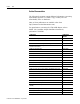
Preface Common Techniques Used in This Manual Publication Publication Number POINT I/O 2 Relay Output Module Installation Instructions (OW2) 1734-IN055 POINT I/O Synchronous Serial Interface Absolute Encoder Module 1734-UM007 POINT I/O Cold Junction Compensation Wiring Base Assembly 1734-IN583 POINT I/O Wiring Base Assembly Installation Instructions 1734-511 POINT I/O 5V dc and 24V dc Very High Speed Counter Module 1734-IN003 Very High Speed Counter Module User Manual 1734-UM003 ControlLogix
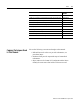
Preface P-4 Terminology Publication 1734-UM008B-EN-P - August 2005 The following table lists ControlNet terminology used throughout this manual. Term Meaning Actual Packet Interval (API) The measure of how frequently a specific connection produces its data. Connection ID (CID) An identifier assigned to a transmission that is associated with a particular connection between producers and consumers that identifies a specific piece of application information.
Chapter 1 About the Module Chapter Objectives This chapter describes the ControlNet adapter (Catalog Number 1734-ACNR) and contains the following main sections. • adapter description and features • hardware components that include diagnostic indicators, a network access port (NAP), and network address switch assemblies This manual addresses the 1734-ACNR, Series A adapter that is compatible with ControlLogix, FlexLogix, and SoftLogix (5800). It is not compatible with PLC-5 and SLC processors.
1-2 About the Module For a description of the diagnostic indicators and status display and how to use them for troubleshooting, see the Diagnostics chapter of this manual.
Chapter 2 Install Your Adapter Chapter Objectives This chapter describes the procedures for installing your adapter, including how to: • • • • • • • Determine Power Requirements determine power requirements set the network address switches install the ControlNet adapter wire the ControlNet adapter connect programming terminals to the network via the NAP install the I/O modules install a replacement adapter to an existing system The 1734-ACNR adapter requires a typical 24V dc power supply with a maxim
2-2 Install Your Adapter Set the Node Address Set the node address using the 2-position thumbwheel switch. Valid settings range from 01 to 99. Press either the + or - buttons to change the number. Module Status Network Node Address thumbwheel press either the + or - buttons to change the number.
Install Your Adapter ATTENTION 2-3 Do not discard the end cap. Use this end cap to cover the exposed interconnections on the last mounting base on the DIN rail. Failure to do so could result in equipment damage or injury from electric shock. Wire the Adapter ATTENTION ATTENTION If you connect or disconnect the communications cable with power applied to this module or any device on the network, an electrical arc can occur. This could cause an explosion in hazardous location installations.
2-4 Install Your Adapter See the figure to guide you in wiring the adapter.
Install Your Adapter Connect Programming Terminals to the Network via the NAP 2-5 You can connect programming terminals to the ControlNet network by connecting to the network access port (NAP), as shown in the figure.
2-6 Install Your Adapter Install the I/O Modules After installing and wiring the adapter, install the POINT I/O modules used for your application.
Install Your Adapter 2-7 1. Remove the existing adapter from the DIN rail as follows. A. Disconnect the ControlNet cable from the adapter. B. Pull up on the RTB removal handle to remove the terminal block. 42511 C. Remove the adjacent module from its base. D. Use a small-bladed screwdriver to rotate the DIN rail locking screw to a vertical position. This releases the locking mechanism. E. Lift straight up to remove. 2. Remove the safety end cap on the replacement adapter by sliding it up.
2-8 Install Your Adapter 8. Reinsert the terminal block by rotating the terminal block into the wiring base until it locks itself into place. 9. Replace the adjacent module in its base. 10. Use a tap to connect the ControlNet cable to the adapter. You must use a tap to connect the adapter to the ControlNet cable. Do not directly connect the adapter to the coax cable.
Chapter 3 Plan to Use Your Adapter Chapter Objectives This chapter explains how the adapter operates on a ControlNet network and provides information to assist in configuring your system. This chapter contains the following information.
3-2 Plan to Use Your Adapter When the 1734-ACNR adapter cannot support any more connections, it does not open the connection and issues the error 0x11a.
Plan to Use Your Adapter Connection Limit Exceeded Error 3-3 The connection limit exceeded error (0x0113) on the Module Properties dialog is shown below. When the 1734-ACNR connection limit is exceeded, you will get an 0x0113 error. The 1734-ACNR connection limit is 600 bytes. This condition can exist when the modules connected to the 1734-ACNR adapter overflow the adapter’s transmit buffer. This condition is rare with most POINT I/O modules.
3-4 Plan to Use Your Adapter Rack Connections A rack connection supports a group of modules. The 1734-ACNR supports five instances of the rack object that provide the ability to communicate I/O data from all discrete I/O modules in the 1734 bus via one connection pair. The rack object contains both I/O and diagnostic status. The rack connection specifies the same fixed size of I/O data for all modules, starting at slot 0 (adapter). IMPORTANT Slot 0 is reserved for the adapter.
Plan to Use Your Adapter 3-5 Direct Connections The 1734-ACNR adapter supports up to 25 direct connections to POINT I/O modules. Multiple controllers can connect to the I/O modules. • The controller that is the first one in will win configuration rights and the ownership of the outputs. • After an owner has established the connection, any other controller can operate in a listen-only mode to a POINT output module.
3-6 Plan to Use Your Adapter Unconnected messaging lets tools or controllers interface with the CIP objects supported by the POINT I/O modules. The adapter lets controllers, scanners, and software applications address objects for POINT I/O modules on the POINTBus using unconnected messaging. This requires the adapter to appear as a bridge to these devices. The POINT I/O modules are directly addressed. The 1734-ACNR adapter is a proxy server for unconnected messaging.
Plan to Use Your Adapter 3-7 The ControlNet system places your scheduled transfers in the first part of each network update interval. Time is automatically reserved for network maintenance. Unscheduled transfers are performed during the time remaining in the interval. You reserve a specific amount of time for all scheduled operations. . . . Any time remaining is used for unscheduled operations. IMPORTANT Before You Begin The system reserves time for network maintenance. . . .
3-8 Plan to Use Your Adapter Configure Autobaud The adapter cannot reconfigure an I/O module that you previously configured to operate at a fixed baud rate. When you reuse a POINT I/O module from another POINT I/O system, configure the module to autobaud before using it with the 1734-ACNR adapter. Understand Adapter Data Capability The 1734-ACNR adapter provides high-speed transfer of time-critical data between controllers and I/O devices.
Plan to Use Your Adapter 3-9 • POINT I/O configuration by itself (number and types of modules) • Type of connection to these modules (direct connection, rack connection) The following example shows a single POINT I/O ControlNet adapter with 5 connections and 8 I/O modules. The POINT I/O modules are monitored by the 5 controllers on the ControlNet network. The POINT I/O modules in the slots are controlled by the controller shown in the table.
3-10 Plan to Use Your Adapter When using I/O modules with large amounts of data, be aware of the 1734-ACNR adapter data capability. The 1734-ACNR adapter has 586 bytes of memory available for scheduled transmit data. The amount of data used by an individual connection must also include a small amount of overhead - 10 bytes per connection. Use the following formula to track the amount of available scheduled transmit data.
Chapter 4 Configure the Adapter Chapter Objectives This chapter guides you through the steps required to configure your 1734 POINT I/O ControlNet adapter using ControlLogix.
4-2 Configure the Adapter The 1784-PCC module is the Personal Computer ControlNet network interface card used to talk to the networks. 2. Start RSLogix5000 Enterprise series software, version 15 or greater. 3. From the File menu, choose New. You see this dialog. 4. • • • • • • Complete the following entries. Type Name Description (optional) Chassis Type Slot Create In 5. Verify that the revision of the controller is compatible with the POINT I/O products.
Configure the Adapter 4-3 Publication 1734-UM008B-EN-P - August 2005
4-4 Configure the Adapter Select a Communication Module 1. Click on I/O Configuration on the left side of the dialog to highlight it. 2. Right-click on I/O Configuration and choose New Module to see this Select Module dialog. 3. Right-click on + next to Communications to expand, as in the following dialog. 4. Choose the 1756-CNBR/D ControlNet Bridge.
Configure the Adapter 4-5 5. Click OK to see the New Module dialog. 6. • • • • • Complete the following entries. Name Node Description (optional) Slot Open Module Properties 7. Click the Open Module Properties box to see the Module Properties dialog when you click OK. 8. Click OK. Notice that the ControlNet_Bridge is under the I/O Configuration.
4-6 Configure the Adapter Select the 1734-ACNR Adapter 1. From the following dialog, right-click on ControlNet and choose New Module. You see the Select Module dialog. 2. Right-click the + next to Communications to see the following dialog. 3. Choose 1734-ACNR/A. 4. Click OK to see the New Module dialog. 5. Make the following entries.
Configure the Adapter 4-7 • Name • Node • Description (optional) 6. Click the Open Module Properties box to see the Module Properties dialog when you click OK. 7. Enter the chassis size using the following guidelines. The chassis size equals 1 for the adapter + the number of POINT I/O modules installed (physically present on the POINT I/O backplane), IMPORTANT The chassis size is the total number of modules installed on the POINTBus backplane. The chassis size includes the POINT I/O adapter.
4-8 Configure the Adapter To identify individual 1734 I/O module publications, use the list of publications in the Preface of this manual. 11. Click OK. Notice that the adapter appears under I/O Configuration.
Configure the Adapter Add Analog, Digital, Other, or Specialty Modules 4-9 Select Analog, Digital, Other, or Speciality, depending on your module type. In this example, we add a digital module. 1. Highlight the 1734-ACNR/A adapter under I/O configuration, right-click, and select New Module . IMPORTANT If you exceed the 1734-ACNR chassis size by trying to add more modules than you configured, the New Module selection is disabled and appears grayed out.
4-10 Configure the Adapter 3. Choose 1734-OB2E/C from the list of modules. 4. Click OK to see the New Module dialog. 5. Enter a name (optional), slot number, and description. 6. Click Change to see the Module Definition dialog. 7. • • • Complete the following entries.
Configure the Adapter 4-11 • Listen-Only - Rack Optimization IMPORTANT Use Rack Optimization and Listen-Only Rack Optimization connections only for discrete I/O modules. Analog and speciality modules require direct connection. For a complete listing of connection types, see: Publication 1734-UM001, POINT I/O Digital and Analog Modules and POINTBus I/O Modules 8. Click OK. Notice that 1734-OB2E is now under the I/O configuration. 9. Click 1734-OB2E to see the New Module dialog. 10.
4-12 Configure the Adapter • • • • Connection Module Info Fault/Program Action Configuration For details on completing entries for Fault/Program Action and Configuration, refer to online help or the user manual for your individual module. 11. Choose Connection to see this Module Properties dialog. 12. Uncheck the following checkboxes, if checked. • Inhibit Module • Major Fault On Controller If Connection Fails While in Run Mode 13. Enter RPI for direct connections.
Configure the Adapter 4-13 14. Choose Module Info to see this dialog, which provides identification and status information. 15. Choose the following for module-specific settings. Refer to the online help and user manual for the applicable modules for details of how to complete the entries on these dialogs. • Fault/Program/Action • Configuration 16. Choose File>Save As and enter the name and location of the RSLogix5000 file.
4-14 Configure the Adapter 3. From the Who Active dialog, choose Set Project Path. 4. From the Who Active dialog, choose Download to see the Download dialog. 5. From the Download dialog, choose Download. You see this RSLogix 5000 dialog.
Configure the Adapter 4-15 Notice that the 1756-CNBR Bridge is now on line, but the rest of the I/O configuration (adapter and I/O modules) connections are not scheduled (notice the yellow triangles). Configure the 1734-ACNR Adapter You have now built the I/O tree in RSLogix5000, and the RSLogix5000 software used the chassis size from the 1734-ACNR General Tab. Now you need to download this new chassis size value into the 1734-ACNR adapter hardware.
4-16 Configure the Adapter 3. Click Set Chassis Size in Module. Value from RSLogix5000 software Value stored in 1734-ACNR adapter Note that these chassis sizes do not match. 4. Read and acknowledge the warning dialog. 5. Click OK to continue. Notice the chassis size in the module has been modified to 4.
Configure the Adapter 4-17 6. Click Apply to update the value in the chassis size module. 7. Click the Connection tab. Notice that the connection request error is still present because we haven’t scheduled any of the I/O module connections yet. You’ll do that through RSNetWorx for ControlNet. Schedule I/O Module Connections Use these procedures to schedule I/O module connections. 1. Start RSNetWorx for ControlNet. 2. From the File menu, choose New. 3. Click OK. 4. Choose Network>Online.
4-18 Configure the Adapter 5. Choose the PCC interface card. 6. Click OK. When you are online, you’ll see the following dialog. You see the Online/Offline mismatch window.
Configure the Adapter 4-19 7. Click OK. 8. Choose Edits Enabled in the top left of the dialog. 9. From the main menu, choose Network>Properties. The _default dialog appears. Specify the following information: 10. Specify a value for Network Update Time - the repetitive time interval in which data can be sent on the link. 11. Specify a value for Max Scheduled Address - the highest number node that has scheduled connections to it. 12.
4-20 Configure the Adapter 13. Specify a value for Media Redundancy on channel A, B or A and B. 14. Click OK to see the Save As dialog. 15. Click Save to see the Save As dialog. 16. From the Save As dialog, enter a name and location for the file, and click Save. You see the Save Configuration dialog. 17. Click OK. 18. Notice the I/O OK is solid green.
Configure the Adapter 4-21 19. Notice that all of the yellow warning triangles are gone in the I/O Configuration. 20. Notice that the Status in the 1734-ACNR Module Properties dialog is Running with no faults. clear of faults Access Module Data via the 1734-ACNR Adapter Use the following information to use the 1734 POINT I/O ControlNet adapter module data in the ladder logic program.
4-22 Configure the Adapter • ACNR:1:C (1734-OB2E module) configuration data • ACNR:1:I (1734-OB2E module) (fault status) input data (open wire and overcurrent) • ACNR:1:O (1734-OB2E module) output data • ACNR:2:C (1734-IB2 module) configuration data Publication 1734-UM008B-EN-P - August 2005
Configure the Adapter 4-23 • ACNR:2:I (1734-IB2 module) input data TIP It is also possible to send configurations via CIP messages.
4-24 Configure the Adapter • ACNR:3:I (1734-IE2V module) input data • ACNR:I or ACNR:O (rack optimized inputs/outputs) Use the controller tags in your ladder program to read input data or write output data. • For RSLogix5000 programming instructions, refer to RSLogix 5000 Configuration and Programming for the Logix5000 Family of Controllers, publication no. RLD300GR. • For ControlLogix controller information, refer to ControlLogix System User Manual, publication 1756-UM001.
Configure the Adapter 4-25 In this example, the 1734-ACNR adapter is using 2 rack optimized connections. Slot 1 is a 1734-OB2E module and slot 2 is a 1734-IB2 module, with both modules installed and operating correctly with 0=no error and 1=connection error (typically, module removed/missing). Change Configuration Data One way to change the configuration data for a POINT I/O module: 1. Enter the new configuration data into the controller tags. 2. Select Module or Adapter in the I/O configuration tree.
4-26 Configure the Adapter 7. Click Apply. 8. Click OK to confirm disabling the connection. The connection is now inhibited. 9. Uncheck the Inhibit Module checkbox to disable the inhibit module function. 10. Click Apply to download the configuration data.
Configure the Adapter 4-27 Note that the connection status is now running. Recover from an Overloaded 1734-ACNR Adapter The overload error (16#000c) appears in the Module Properties dialog. This is a recoverable fault. Once the 1734-ACNR adapter determines that it is overloaded, it drops all connections. It will refuse all connections until you take action reset or power cycle the 1734-ACNR adapter, or repair any bad input devices and wiring to I/O modules. The 1734-ACNR adapter will behave as follows.
4-28 Configure the Adapter • The 1734-ACNR adapter removes all of its ControlNet connections. • The 1734-ACNR adapter enters into a state where connections are not permitted. • The 1734-ACNR adapter responds to any connection request with a unique error. General Status 0x0C is the unique error code that identifies the 1734-ACNR overload mode. • The1 734-ACNR Adapter Status LED flashes red, indicating a recoverable fault. • In this no connections allowed state, the adapter continues to process messages.
Chapter 5 Diagnostics Use the Indicators to Troubleshoot Use these indicators to help troubleshoot problems with the adapter.
5-2 Diagnostics Indication Probable Cause Module Status Off No power applied to device Alternating Red/Green LED powerup test (module self-test) Flashing Red Recoverable fault has occurred: • Firmware (NVS) update • MAC ID changed • CPU load exceeded Solid Red Unrecoverable fault has occurred: • self test failure (checksum failure at powerup, ramtest failure at powerup) • firmware fatal error Flashing Green Waiting for connection or ControlNet cable break Solid Green Module is operating corre
Diagnostics 5-3 POINTBus Status Off Device not powered - check module status indicator Alternating Red/Green LED powerup test Flashing Red Recoverable fault has occurred: • at power up the number of expected modules does not equal the number of modules present • a module is missing • node fault (I/O connection timeout) • after power-up of I/O modules is taking place • collecting identities • verifying configuration Red Unrecoverable fault has occurred: • Adapter is bus off • Adapter has failed its
5-4 Diagnostics Notes: Publication 1734-UM008B-EN-P - August 2005
Appendix A 1734-POINT I/O Module/RSLogix5000 Controller Tag Reference 1734 POINT I/O Catalog Numbers 1734 POINT I/O Catalog Number RSLogix5000 Module Description Digital Modules 1734-IA2/C 2 POINT 120V AC Input 1734-IB2/C 2 POINT 10V-28V DC Input, Sink 1734-IB4/C 4 POINT 10V-28V DC Input, Sink 1734-IM2/C 2 POINT 240V AC Input 1734-IV2/C 2 POINT 10V-28V DC Input, Source 1734-IV4/C 4 POINT 10V-28V DC Input, Source 1734-OA2/C 2 POINT 120V AC Output 1734-OB2E/C 2 POINT 10V-28V DC Electronic
A-2 1734-POINT I/O Module/RSLogix5000 Controller Tag Reference 1734 POINT I/O Catalog Number RSLogix5000 Module Description Specialty I/O 1734-232ASC/C 1 Channel ASCII Interface Module 1734-IJ/C 1 Channel 5V DC Encoder/Counter 1734-IK/C 1 Channel 15-24V DC Encoder/Counter 1734-SSI/C 1 Channel Synchronous Serial Interface 1734-VHSC24/C 1 Channel 15-24V DC Very High Speed Counter 1734-VHSC5/C 1 Channel 5V DC Very High Speed Counter Note that all POINT I/O modules must be Series C or above for
1734-POINT I/O Module/RSLogix5000 Controller Tag Reference A-3 Discrete 2 POINT Input 1734-IA2 2 POINT 120V AC Input 1734-IB2 2 POINT 10V-28V DC Input, Sink 1734-IM2 2 POINT 240V AC Input 1734-IV2 2 POINT 10V-28V DC Input, Source Configuration Data Data Type Default Value Valid Data Values Filter Off On Time - POINT 0 INT 1,000 -32,768 to 32,767 µs * (0 - 65,535) Filter On Off Time - POINT 0 INT 1,000 -32,768 to 32,767 µs * (0 - 65,535) Filter Off On Time - POINT 1 INT 1,000 -32,768 to 32,7
A-4 1734-POINT I/O Module/RSLogix5000 Controller Tag Reference Discrete 4 POINT Input 1734-IB4 4 POINT 10V-28V DC Input, Sink 1734-IV4 4 POINT 10V-28V DC Input, Source Configuration Data Data Type Default Value Valid Data Values Filter Off On Time - POINT 0 INT 1,000 -32,768 to 32,767 µs * (0 - 65,535) Filter On Off Time - POINT 0 INT 1,000 -32,768 to 32,767 µs * (0 - 65,535) Filter Off On Time - POINT 1 INT 1,000 -32,768 to 32,767 µs * (0 - 65,535) Filter On Off Time - POINT 1 INT 1,000
1734-POINT I/O Module/RSLogix5000 Controller Tag Reference A-5 Filter Time Note To enter Filter values from +32,768 to +65,535 µs, use this conversion formula: Desired Filter Value (in µs) - 65536 = Entered Filter Value (in µs). Example: For a 40ms filter time, 40000 - 65536 = -25536 Discrete 2 POINT Output – Without Diagnostic Status 1734-OA2 2 POINT 120V AC Output 1734-OW2 2 POINT AC/DC Relay Output 1734-OX2 2 POINT Relay Output N.O./N.C.
A-6 1734-POINT I/O Module/RSLogix5000 Controller Tag Reference Discrete 2 POINT Output – With Over Load and Open Load Diagnostic Status Publication 1734-UM008B-EN-P - August 2005 1734-OB2E 2 POINT 10V-28V DC Electronically Fused Output, Source 1734-OB2EP 2 POINT 10V-28V DC Electronically Fused Protected Output, Source Configuration Data Data Type Default Value Valid Data Values Fault Mode - POINT 0, 1 SINT, BIT 0 0=Fault Value 1=Hold Last State Fault Value - POINT 0, 1 SINT, BIT 0 0=Off 1=On
1734-POINT I/O Module/RSLogix5000 Controller Tag Reference Discrete 2 POINT Output – With Over Load Diagnostic Status A-7 1734-OV2E 2 POINT 10V-28V DC Electronically Fused Output, Sink Configuration Data Data Type Default Value Valid Data Values Fault Mode - POINT 0, 1 SINT, BIT 0 0=Fault Value 1=Hold Last State Fault Value - POINT 0, 1 SINT, BIT 0 0=Off 1=On Program Mode - POINT 0, 1 SINT, BIT 0 0=Program Value 1=Hold Last State Program Value - POINT 0, 1 SINT, BIT 0 0=Off 1=On Auto
A-8 1734-POINT I/O Module/RSLogix5000 Controller Tag Reference Discrete 4 POINT Output – With Over Load and Open Load Diagnostic Status Publication 1734-UM008B-EN-P - August 2005 1734-OB4E 4 POINT 10V-28V DC Electronically Fused Output, Source Configuration Data Data Type Default Value Valid Data Values Fault Mode - POINT 0, 1, 2, 3 SINT, BIT 0 0=Fault Value 1=Hold Last State Fault Value - POINT 0, 1, 2, 3 SINT, BIT 0 0=Off 1=On Program Mode - POINT 0, 1, 2, 3 SINT, BIT 0 0=Program Value
1734-POINT I/O Module/RSLogix5000 Controller Tag Reference Discrete 4 POINT Output – With Over Load Diagnostic Status A-9 1734-OV4E 4 POINT 10V-28V DC Electronically Fused Output, Sink Configuration Data Data Type Default Value Valid Data Values Fault Mode - POINT 0, 1, 2, 3 SINT, BIT 0 0=Fault Value 1=Hold Last State Fault Value - POINT 0, 1, 2, 3 SINT, BIT 0 0=Off 1=On Program Mode - POINT 0, 1, 2, 3 SINT, BIT 0 0=Program Value 1=Hold Last State Program Value - POINT 0, 1, 2, 3 SINT, B
A-10 1734-POINT I/O Module/RSLogix5000 Controller Tag Reference Analog 2 Channel Input 1734-IE2C 2 Channel Analog Current Input Publication 1734-UM008B-EN-P - August 2005 Configuration Data Data Type Default Value Valid Data Values Low Engineering Channel 0 INT 3,277 -32,768 to 32,767 High Engineering Channel 0 INT 16,383 -32,768 to 32,767 Digital Filter Channel 0 INT 0 0 to 10,000 ms Low Alarm Limit Channel 0 INT 3,113 -32,768 to 32,767 High Alarm Limit Channel 0 INT 16,547 -32,7
1734-POINT I/O Module/RSLogix5000 Controller Tag Reference A-11 1734-IE2C 2 Channel Analog Current Input Input Data Data Type Default Value Valid Data Values Data Channel 0 INT 0 -32,768 to 32,767 Data Channel 1 INT 0 -32,768 to 32,767 Status Byte Channel 0 SINT 0 Bit 0 Fault Bit 1 Calibration Bit 2 LowAlarm Bit 3 HighAlarm Bit 4 LowLowAlarm Bit 5 HighHighAlarm Bit 6 Underrange Bit 7 Overrange Status Byte Channel 1 SINT 0 Bit 0 Fault Bit 1 Calibration Bit 2 LowAlarm Bit 3 HighAlarm Bit
A-12 1734-POINT I/O Module/RSLogix5000 Controller Tag Reference 1734-IE2V 2 Channel Analog Voltage Input Publication 1734-UM008B-EN-P - August 2005 Configuration Data Data Type Default Value Valid Data Values Low Engineering Channel 0 INT 0 -32,768 to 32,767 High Engineering Channel 0 INT 10,000 -32,768 to 32,767 Digital Filter Channel 0 INT 0 0 to 10,000 ms Low Alarm Limit Channel 0 INT 500 -32,768 to 32,767 High Alarm Limit Channel 0 INT 9,500 -32,768 to 32,767 Low Low Alarm Li
1734-POINT I/O Module/RSLogix5000 Controller Tag Reference A-13 1734-IE2V 2 Channel Analog Voltage Input Input Data Data Type Default Value Valid Data Values Data Channel 0 INT 0 -32,768 to 32,767 Data Channel 1 INT 0 -32,768 to 32,767 Status Byte Channel 0 SINT 0 Bit 0 Fault Bit 1 Calibration Bit 2 LowAlarm Bit 3 HighAlarm Bit 4 LowLowAlarm Bit 5 HighHighAlarm Bit 6 Underrange Bit 7 Overrange Status Byte Channel 1 SINT 0 Bit 0 Fault Bit 1 Calibration Bit 2 LowAlarm Bit 3 HighAlarm Bit
A-14 1734-POINT I/O Module/RSLogix5000 Controller Tag Reference 1734-IR2 2 Channel RTD Input Configuration Data Data Type Default Value Valid Data Values Low Engineering Channel 0 INT 1,000 -32,768 to 32,767 High Engineering Channel 0 INT 5,000 -32,768 to 32,767 Digital Filter Channel 0 INT 0 0 to 10,000 ms Low Alarm Limit Channel 0 INT -32,768 -32,768 to 32,767 High Alarm Limit Channel 0 INT 32,767 -32,768 to 32,767 Low Low Alarm Limit Channel 0 INT -32,768 -32,768 to 32,767 H
1734-POINT I/O Module/RSLogix5000 Controller Tag Reference A-15 1734-IR2 2 Channel RTD Input Configuration Data Data Type Default Value Valid Data Values Sensor Type Channel 1 SINT 1 0=Ohms 1=100 Ω Pt α385 2=200 Ω Pt α385 5=100 Ω JPt α3916 6=200 Ω JPt α3916 9=10 Ω Cu α427 10=120 Ω Ni α672 11=100 Ω Ni α618 12=120 Ω Ni α618 Temperature Mode Channel 1 SINT 1 0=Custom Scale 1=°C 2=°F 3=°K 4=°R Notch Filter (Channel 0 & 1) SINT 1 0=50Hz 1=60Hz 2=100Hz 3=120Hz 4=200Hz 5=240Hz 6=300Hz 7=400Hz 8=48
A-16 1734-POINT I/O Module/RSLogix5000 Controller Tag Reference 1734-IT2 2 Channel Thermocouple Input, Isol.
1734-POINT I/O Module/RSLogix5000 Controller Tag Reference A-17 1734-IT2 2 Channel Thermocouple Input, Isol. Configuration Data Data Type Default Value Valid Data Values Temperature Mode Channel 0 SINT 1 0=mV/Custom Scale 1=°C 2=°F 3=°K 4=°R Cold Junction Enable Channel 0 SINT 1 0=Disabled 1=Enabled Cold Junction Offset Channel 0 INT 0 0 to 7,000 (0.00-70.
A-18 1734-POINT I/O Module/RSLogix5000 Controller Tag Reference 1734-IT2 2 Channel Thermocouple Input, Isol. Configuration Data Data Type Default Value Valid Data Values Temperature Mode Channel 1 SINT 1 0=mV/Custom Scale 1=°C 2=°F 3=°K 4=°R Cold Junction Enable Channel 1 SINT 1 0=Disabled 1=Enabled Cold Junction Offset Channel 1 INT 0 0 to 7,000 (0.00-70.
1734-POINT I/O Module/RSLogix5000 Controller Tag Reference A-19 Analog 2 Channel Output 1734-OE2C 2 Channel Analog Current Output Configuration Data Data Type Default Value Valid Data Values Fault Value Channel 0 INT 0 -32,768 to 32,767 Program Value Channel 0 INT 0 -32,768 to 32,767 Low Engineering Channel 0 INT 1,638 -32,768 to 32,767 High Engineering Channel 0 INT 8,191 -32,768 to 32,767 Low Limit Channel 0 INT -32,768 -32,768 to 32,767 High Limit Channel 0 INT 32,767 -32,768
A-20 1734-POINT I/O Module/RSLogix5000 Controller Tag Reference 1734-OE2C 2 Channel Analog Current Output Publication 1734-UM008B-EN-P - August 2005 Configuration Data Data Type Default Value Valid Data Values Idle Mode Channel 1 SINT 1 0=Hold Last State 1=Go to Low Clamp 2=Go to High Clamp 3=Go to Fault Value Limit Alarm Latch Channel 1 SINT 0 0=No Latching 1=Alarms Latch Alarm Disable Channel 1 SINT 0 0=Alarms Enabled 1=Alarms Disabled Input Data Data Type Default Value Valid Data V
1734-POINT I/O Module/RSLogix5000 Controller Tag Reference A-21 1734-OE2V 2 Channel Analog Voltage Output Configuration Data Data Type Default Value Valid Data Values Fault Value Channel 0 INT 0 -32,768 to 32,767 Program Value Channel 0 INT 0 -32,768 to 32,767 Low Engineering Channel 0 INT 0 -32,768 to 32,767 High Engineering Channel 0 INT 10,000 -32,768 to 32,767 Low Limit Channel 0 INT -32,768 -32,768 to 32,767 High Limit Channel 0 INT 32,767 -32,768 to 32,767 Range Type Chan
A-22 1734-POINT I/O Module/RSLogix5000 Controller Tag Reference 1734-OE2V 2 Channel Analog Voltage Output Publication 1734-UM008B-EN-P - August 2005 Configuration Data Data Type Default Value Valid Data Values Limit Alarm Latch Channel 1 SINT 0 0=No Latching 1=Alarms Latch Alarm Disable Channel 1 SINT 0 0=Alarms Enabled 1=Alarms Disabled Input Data Data Type Default Value Valid Data Values Status Byte Channel 0 SINT 0 Bit 0 Fault Bit 1 Calibration Bit 2 LowAlarm Bit 3 HighAlarm Statu
1734-POINT I/O Module/RSLogix5000 Controller Tag Reference A-23 Specialty I/O 1734-VHSC24 1 Channel 15-24V DC Very High Speed Counter 1734-VHSC5 1 Channel 5V DC Very High Speed Counter Configuration Data Data Type Default Value Valid Data Values Counter Config Config_0 Config_1 Config_2 Config_3 SINT BIT 0 BIT 1 BIT 2 BIT 3 0 Mode_4 Mode_5 Mode_6 BIT 4 BIT 5 BIT 6 000=Store Count Disable 001=Store/Continue 010=Store/Wait/Resume 011=Store,Reset/Wait/Start 100=Store,Reset/Start Z Input BIT 7 0=Z
A-24 1734-POINT I/O Module/RSLogix5000 Controller Tag Reference 1734-VHSC24 1 Channel 15-24V DC Very High Speed Counter 1734-VHSC5 1 Channel 5V DC Very High Speed Counter Publication 1734-UM008B-EN-P - August 2005 Configuration Data Data Type Default Value Valid Data Values Scalar SINT 0 Counter Config 5, 6, 8 only: -128 to +127 (0 - 255) Single Bit only: 0, 1, 2, 4, 8, 16, 32, 64, -128 Output Ties 0 Out 0 Window 1 Out 0 Window 2 Out 0 Window 3 Out 0 Window 4 SINT BIT 0 BIT 1 BIT 2 BIT 3 0 Ou
1734-POINT I/O Module/RSLogix5000 Controller Tag Reference A-25 1734-VHSC24 1 Channel 15-24V DC Very High Speed Counter 1734-VHSC5 1 Channel 5V DC Very High Speed Counter Configuration Data Data Type Default Value SS Output Control SS Out 0 Force SINT BIT 0 0 SS Out 0 En BIT 1 SS Out 0 Electronic Fuse BIT 2 SS Out 0 Diagnostic Speed BIT 3 SS Out 1 Force BIT 4 SS Out 1 En BIT 5 SS Out 1 Electronic Fuse BIT 6 SS Out 1 Diagnostic Speed BIT 7 Valid Data Values 0=Output Off 1=Output Forced
A-26 1734-POINT I/O Module/RSLogix5000 Controller Tag Reference Input Data Data Type Default Value Valid Data Values Present Data DINT 0 0 to 16,777,215 Stored Data DINT 0 -2,147,483,648 to 2,147,483,647 (0 - 4,294,967,295) Status Zero Frequency Detected INT BIT 1 0 0=No Fault 1=Fault Detected Stored Data Count_2 Stored Data Count_3 BIT 2 BIT 3 Cycles thru 0, 1, 2, 3, 0, Increments after update A Input Status B Input Status Z Input Status BIT 4 BIT 5 BIT 6 0=Input A/B/Z is Off 1=Input
1734-POINT I/O Module/RSLogix5000 Controller Tag Reference A-27 Program Fault Note Programming Fault Error bit - If an incomplete, incorrect, or conflicting set of configuration parameters are sent to the module, the Program Fault bit will be asserted and an error code will be placed in the Programming error Code word (assembly 6816). The module will not enter a normal operational state.
A-28 1734-POINT I/O Module/RSLogix5000 Controller Tag Reference 1734-VHSC24 1 Channel 15-24V DC Very High Speed Counter 1734-VHSC5 1 Channel 5V DC Very High Speed Counter Output Data Data Type Default Value Valid Data Values PWM Value INT 0 0 to 9500 (0.00% to 95.
1734-POINT I/O Module/RSLogix5000 Controller Tag Reference A-29 1734-IJ 1 Channel 5V DC Encoder / Counter 1734-IK 1 Channel 15-24V DC Encoder / Counter Configuration Data Data Type Default Value Counter Config Config_0 Config_1 Config_2 Config_3 SINT BIT 0 BIT 1 BIT 2 BIT 3 0 Mode_4 Mode_5 Mode_6 BIT 4 BIT 5 BIT 6 Z Input BIT 7 Filter Filter_0 Filter_1 Filter_2 Filter_3 SINT BIT 0 BIT 1 BIT 2 BIT 3 FilterA FilterB FilterZ BIT 4 BIT 5 BIT 6 Valid Data Values 0000=0=Counter 0001=1=Encoder X1
A-30 1734-POINT I/O Module/RSLogix5000 Controller Tag Reference 1734-IJ 1 Channel 5V DC Encoder / Counter 1734-IK 1 Channel 15-24V DC Encoder / Counter Configuration Data Data Type Default Value SS Counter Control SS Counter Reset SINT BIT 0 0 SS Counter Preset BIT 1 SS Value Reset BIT 2 Valid Data Values 0=Count Unchanged 1=Count Cleared 0=Count Unchanged 1=Count Set to Preset 0=Count Unchanged 1=Count Cleared To enter values from +128 to +255, use these conversion formulas: Decimal Position
1734-POINT I/O Module/RSLogix5000 Controller Tag Reference A-31 1734-IJ 1 Channel 5V DC Encoder / Counter 1734-IK 1 Channel 15-24V DC Encoder / Counter Input Data Data Type Default Value Valid Data Values Present Data DINT 0 0 to 16,777,215 Stored Data DINT 0 -2,147,483,648 to 2,147,483,647 (0 - 4,294,967,295) Status Zero Frequency Detected INT BIT 1 0 Stored Data Count_2 Stored Data Count_3 BIT 2 BIT 3 Cycles thru 0, 1, 2, 3, 0, Increments after update A Input Status B Input Status Z In
A-32 1734-POINT I/O Module/RSLogix5000 Controller Tag Reference Program Fault Note Programming Fault Error bit - If an incomplete, incorrect, or conflicting set of configuration parameters are sent to the module, the Program Fault bit will be asserted and an error code will be placed in the Programming error Code word (assembly 6816). The module will not enter a normal operational state.
1734-POINT I/O Module/RSLogix5000 Controller Tag Reference A-33 1734-IJ 1 Channel 5V DC Encoder / Counter 1734-IK 1 Channel 15-24V DC Encoder / Counter Output Data Data Type Default Value Counter Control Counter Reset SINT BIT 0 0 0 Counter Preset BIT 1 0 Value Reset (Stored / Accumulated Count) BIT 2 0 Valid Data Values 0=Count Unchanged 1=Count Cleared 0=Count Unchanged 1=Count Set to Preset 0=Count Unchanged 1=Count Cleared Publication 1734-UM008B-EN-P - August 2005
A-34 1734-POINT I/O Module/RSLogix5000 Controller Tag Reference 1734-SSI 1 Channel Synchronous Serial Interface Configuration Data Data Type Default Value Valid Data Values Run SINT 1 0=Module Not Running 1=Module Is Running Gray Binary SINT 1 0=Binary Code 1=Gray Code Word Length SINT 13 2 to 31 Data Speed SINT 5 5=125K Baud 6=250K Baud 7=500K Baud 8=1M Baud 9=2M Baud G2B Convert (Gray to Binary) SINT 0 0=No Convert 1=Convert Standardization (Divide / Shift using Trailing) SINT
1734-POINT I/O Module/RSLogix5000 Controller Tag Reference A-35 1734-SSI 1 Channel Synchronous Serial Interface Configuration Data Data Type Default Value Valid Data Values Compare 1 Control; Compare1_0 Compare1_1 SINT BIT 0 BIT 1 0 00=Off 01=Up Direction 10=Down Direction 11=Both Directions SSI Word Delay Time Note: To enter Delay values from +32,768 to +65,535 µs, use this conversion formula: Desired Delay Value (in µs) - 65536 = Entered Delay Value (in µs).
A-36 1734-POINT I/O Module/RSLogix5000 Controller Tag Reference Compare 0,1 Value Note: To enter Compare values from +2,147,483,647 to +4,294,967,295, use this conversion formula: Desired Compare Value - 4,294,967,296 = Entered Compare Value.
1734-POINT I/O Module/RSLogix5000 Controller Tag Reference A-37 Present / Latched Data Note: To interpret values from -2,147,483,648 to -1, use this conversion formula: Stored Data Tag Value + 4,294,967,296 = Actual Stored Data Tag Value.
A-38 1734-POINT I/O Module/RSLogix5000 Controller Tag Reference 1734-232ASC 1 Channel ASCII Interface Module Configuration Data Data Type Default Value Valid Data Values Serial Character Format (ASCII Format: Data Bits / Parity / Stop) SINT 0 0=7N2 1=7E1 2=7O1 3=8N1 4=8N2 5=8E1 6=8O1 7=7E2 8=7O2 Serial Comm Speed (Baud Rate of the Serial Port) SINT 0 0=9600 1=1200 2=2400 3=4800 4=19.2K 5=38.
1734-POINT I/O Module/RSLogix5000 Controller Tag Reference A-39 1734-232ASC 1 Channel ASCII Interface Module Configuration Data Data Type Default Value Valid Data Values Transmit End Delimiter Mode SINT 2 0=No End Delimiter 1=Exclude End Delimiter 2=Include End Delimiter Transmit End Delimiter Character SINT 13 (0x0d) Any Valid ASCII Character (Default is Carr.
A-40 1734-POINT I/O Module/RSLogix5000 Controller Tag Reference 1734-232ASC 1 Channel ASCII Interface Module Input Data Data Type Default Value Valid Data Values Receive Record Number SINT 0 -128 to +127 (0 - 255) Status TX FIFO Overflow SINT BIT 0 0 RX FIFO Overflow BIT 1 RX Parity Error BIT 2 Handshake Error BIT 6 New Data Flag BIT 7 Length_Lo SINT 20 -128 to +127 (0 - 128) Length_Hi SINT 0 0 or 1 Data[128] SINT 0 Received ASCII Message Output Data Data Type Default Valu
1734-POINT I/O Module/RSLogix5000 Controller Tag Reference A-41 Transmit Record Number/ Receive Record Number / Length_Lo Note: Note that “7 data bits” allows Transmit / Receive record Number of Length_Lo values of 0 - 127, which RSLogix5000 does support in the signed Short Integer data type SINT (-128 to +127 range). Note that “8 data bits” allows Transmit / Receive record Number of Length_Lo values of 0 - 255.
A-42 1734-POINT I/O Module/RSLogix5000 Controller Tag Reference Notes: Publication 1734-UM008B-EN-P - August 2005
Index Numbers 1734-ACNR configure 4-1 controller tag reference A-1 diagnostic indicators 1-2 diagnostics 5-1 features 1-1 hardware components 1-2 indicators 5-1 installing 2-1 module description 1-1 network access port (NAP) 1-3 network address switch assemblies 1-3 plan to use 3-1 1734-POINT I/O catalog numbers A-1 A adapter operations direct connections 3-5 explicit messaging communications 3-5 I/O connections 3-1 overview 3-1 rack connections 3-4 software and hardware requirements 3-6 adding modules to
2 Index I I/O connections 3-1 I/O modules installing 2-4 indicators 5-1 installing 2-1 adapter 2-2 connect terminals to NAP 2-4 determine power requirements 2-1 I/O modules 2-4 replacement adapter 2-5 set node address 2-2 wire the adapter 2-3 Installing I/O Modules 2-4 Installing the Adapter 4-23 M module data access 4-19 N network access port (NAP) 1-3 network address switch assemblies 1-3 node address setting 2-2 determining 2-1 program fault note A-27, A-32 programming terminal connecting to network
How Are We Doing? Your comments on our technical publications will help us serve you better in the future. Thank you for taking the time to provide us feedback. You can complete this form and mail (or fax) it back to us or email us at RADocumentComments@ra.rockwell.com Pub. Title/Type POINT I/O ControlNet Adaptert Cat. No. Pub. No. 1734-ACNR 1734-UM008B-EN-P Pub. Date August 2005 Part No. 957974-14 Please complete the sections below.
PLEASE FASTEN HERE (DO NOT STAPLE) PLEASE FOLD HERE NO POSTAGE NECESSARY IF MAILED IN THE UNITED STATES BUSINESS REPLY MAIL FIRST-CLASS MAIL PERMIT NO.
Rockwell Automation Support Rockwell Automation provides technical information on the web to assist you in using its products. At http://support.rockwellautomation.com, you can find technical manuals, a knowledge base of FAQs, technical and application notes, sample code and links to software service packs, and a MySupport feature that you can customize to make the best use of these tools.