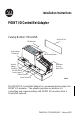
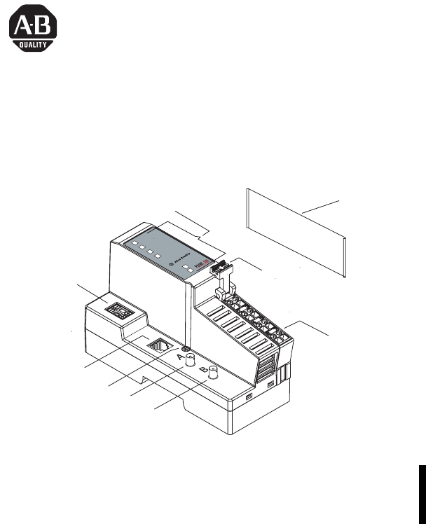
Installation Instructions POINT I/O ControlNet Adapter Catalog Number 1734-ACNR Safety End Cap tA tB 17 34 -A CN R C Sta ontr tu olN s e C Sta ontr tu olN s e P Sta oin tu tBu s s M Sta od tu ule s LED Indicators Sy Po ste Fie we m Po ld r w er Node Address Thumbwheel 2 RTB Removal Handle Network Address Port (NAP) DIN Rail Locking Screw (orange) Removable Terminal Block (RTB) Coaxial Channel A Coaxial Channel B 43247A 43247 The POINT I/O ControlNet Adapter is a communications adapter
Important User Information Because of the variety of uses for the products described in this publication, those responsible for the application and use of these products must satisfy themselves that all necessary steps have been taken to assure that each application and use meets all performance and safety requirements, including any applicable laws, regulations, codes and standards.
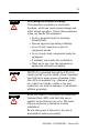
WARNING ATTENTION IMPORTANT BURN HAZARD SHOCK HAZARD Identifies information about practices or circumstances that can cause an explosion in a hazardous environment, which may lead to personal injury or death, property damage, or economic loss. Identifies information about practices or circumstances that can lead to personal injury or death, property damage, or economic loss. Identifies information that is critical for successful application and understanding of the product.
Environment and Enclosure This equipment is intended for use in a Pollution Degree 2 industrial environment, in overvoltage Category II applications (as defined in IEC publication 60664-1), at altitudes up to 2000 meters without derating. This equipment is considered Group 1, Class A industrial equipment according to IEC/CISPR Publication 11.
ATTENTION Preventing Electrostatic Discharge This equipment is sensitive to electrostatic discharge, which can cause internal damage and affect normal operation. Follow these guidelines when you handle this equipment: • Touch a grounded object to discharge potential static. • Wear an approved grounding wriststrap. • Do not touch connectors or pins on component boards. • Do not touch circuit components inside the equipment. • If available, use a static-safe workstation.
Before You Begin To effectively use your adapter, note the following considerations. Understand Messaging Class 3 (Explicit Message) requests through the 1734-ACNR adapter to a specific POINT I/O module may not always receive a response from the I/O module. In the case where the I/O module does not reply to the request, the adapter responds with an error code indicating a time-out.
Install the ControlNet Adapter ATTENTION You must use Series C Point I/O modules with the 1734-ACNR. Series A and B Point I/O modules will not work with the 1734-ACNR. To install the adapter on the DIN rail prior to installing other base units, proceed as follows. 1. Position the adapter vertically above the DIN rail. 2. Press down firmly to install the adapter on the DIN rail. The locking mechanism will lock the adapter to the DIN rail. 3. Set the node address on the node address thumbwheel.
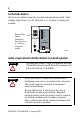
Set the Node Address Set the node address using the 2-position thumbwheel switch. Valid settings range from 01 to 99. Press the + or - buttons to change the number. Module Status Network Node Address thumbwheel Press either the + or - buttons to change the number.
1. Remove the existing adapter from the DIN rail as follows: a. Disconnect the ControlNet connector from the adapter. b. Pull up on the RTB removal handle to remove the terminal block. c. Remove the adjacent module from its base. d. Use a small bladed screwdriver to rotate the DIN rail locking screw to a vertical position. This releases the locking mechanism. e. Lift straight up to remove 2. Remove the safety end cap on the replacement adapter by sliding it up.
Wire the ControlNet Adapter WARNING WARNING If you connect or disconnect the communications cable with power applied to this module or any device on the network, an electrical arc can occur. This could cause an explosion in hazardous location installations. If you connect or disconnect wiring while the field-side power is on, an electrical arc can occur. This could cause an explosion in hazardous location installations. Be sure that power is removed or the area is nonhazardous before proceeding.
Module Status PointBus ControlNet A ControlNet B Module Status Node Address 0 2 PointBus Status ControlNet A Status ControlNet B Status 1734-ACNR Network System Power Field Power System Power Field Power A Coaxial NC B CHAS GND Coaxial C NC = No Connection V 12/24V 0 43264 1 NC NC Do not connect 2 3 120/240V ac CHAS CHAS 4 V dc C C V V 6 5 7 30880 This dc supply will be connected to NC = No Connection C= Publication 1734-IN582B-EN-P - February 2005
Troubleshoot with the Indicators 0 2 Module Status Module Status PointBus Status PointBus Status ControlNet A Status ControlNet A ControlNet B ControlNet B Status 1734-ACNR A System Power B Field Power System Power Field Power 43265 Indication Probable Cause Field Power Off Not active; field power is off Green Power on; 24V present System Power Off Not active; field power is off or dc-dc converter problem Green System power on; dc-dc converter active (5V) Module Status Off No po
Solid Red Unrecoverable fault has occurred: self test failure (checksum failure at powerup, ramtest failure at powerup) firmware fatal error Flashing Green Waiting for connection or ControlNet cable break Solid Green Module is operating correctly (normal mode) ControlNet A/B Status Viewed Together Both Steady Off Reset, no power or entire network interface deactivated Alternating Red/Green Self test mode Alternating Red/Off Bad/invalid node configuration (such as duplicate MAC ID) Both Steady
Red Unrecoverable fault has occurred: • The adapter is bus off • The adapter has failed its duplicate MAC ID check Flashing Green Adapter on-line with no connections established • adapter chassis size has not been configured • controller in program/idle mode • ControlNet cable break Green Adapter on-line with connections established (normal operation, in run mode) ControlNet A/B Status Viewed Together Both Steady Off Reset, no power or entire network interface deactivated Alternating Red/Green S
North American Hazardous Location Approval The following information applies when operating this equipment in hazardous locations: Informations sur l’utilisation de cet équipement en environnements dangereux : Products marked “CL I, DIV 2, GP A, B, C, D” are suitable for use in Class I Division 2 Groups A, B, C, D, Hazardous Locations and nonhazardous locations only. Each product is supplied with markings on the rating nameplate indicating the hazardous location temperature code.
European Hazardous Location Approval European Zone 2 Certification (The following applies when the product bears the EEx Marking) This equipment is intended for use in potentially explosive atmospheres as defined by European Union Directive 94/9/EC.
Specifications Specifications - 1734-ACNR ControlNet Adapter Expansion I/O Capacity Maximum of 63 modules Maximum of 5 Rack Optimized connections (for digital modules only) Maximum of 25 Direct connections 1734-ACNR backplane current output = 1.0A maximum. See list following for backplane current consumption for each Point I/O catalog number and current consumption for each of the Point modules connected to the 1734-ACNR. Verify it is below 1.0A. Backplane current can be extended beyond 1.
Specifications - 1734-ACNR ControlNet Adapter (continued) Expansion I/O Capacity Cat. No.
Power Supply Specifications Input Voltage Rating 24V dc nominal 10-28.8V dc range Field Side Power Requirements 24V dc (+20% = 28.8V dc maximum) @ 425mA maximum Inrush Current 6A maximum for 10ms Interruption Output voltage will stay within specifications when input drops out for 10ms at 10V with maximum load.
ESD Immunity IEC 61000-4-2: 6kV contact discharges 8kV air discharges Radiated RF Immunity IEC 61000-4-3: 10V/m with 1kHz sine-wave 80%AM from 30MHz to 2000MHz 10V/m with 200Hz 50% pulse 100%AM from 900MHz EFT/B Immunity IEC 61000-4-4: +4kV at 5.0kHz on power ports +2kV at 5.
Environmental Conditions Operational Temperature IEC 60068-2-1 (Test Ad, Operating Cold), IEC 60068-2-2 (Test Bd, Operating Dry Heat), IEC 60068-2-14 (Test Nb, Operating Thermal Shock): -20 to 55° C (-4 to 131° F) Storage Temperature IEC 60068-2-1 (Test Ab, Unpackaged Nonoperating Cold), IEC 60068-2-2 (Test Bb, Unpackaged Nonoperating Dry Heat), IEC 60068-2-14 (Test Na, Unpackaged Nonoperating Thermal Shock): -40 to 85° C (-40 to 185° F) Relative Humidity IEC 60068-2-30 (Test Db, Unpackaged Nonoper
Certifications3 (when product is marked) c-UL-us UL Listed for Class I, Division 2 Group A,B,C,D Hazardous Locations, certified for U.S. and Canada EEX European Union 94/9/EC ATEX Directive, compliant with: EN 50021; Potentially Explosive Atmospheres, Protection “n” (Zone 2) CE European Union 89/336/EEC EMC Directive, compliant with: EN 61000-6-4; Industrial Emissions EN 50082-2; Industrial Immunity EN 61326; Meas./Control/Lab.
Notes: Publication 1734-IN582B-EN-P - February 2005
Rockwell Automation Support Rockwell Automation provides technical information on the web to assist you in using its products. At http://support.rockwellautomation.com, you can find technical manuals, a knowledge base of FAQs, technical and application notes, sample code and links to software service packs, and a MySupport feature that you can customize to make the best use of these tools.