Installation Instructions POINT I/O Module with 8 Configurable 24V DC Points and DeviceLogix Catalog Numbers 1734-8CFGDLX Topic Page Important User Information 2 Environment and Enclosure 3 Prevent Electrostatic Discharge 4 About the Module 4 Before You Begin 5 Install the Mounting Base 6 Install the Module 7 Install the Removable Terminal Block 9 Wire the Module 11 Wiring Diagram 12 Configure the Module 13 Interpret the Indicators 20 Specifications 23
POINT I/O Module with 8 Configurable 24V DC Points and DeviceLogix Important User Information Solid state equipment has operational characteristics differing from those of electromechanical equipment. Safety Guidelines for the Application, Installation and Maintenance of Solid State Controls (Publication SGI-1.1 available from your local Rockwell Automation sales office or online at http://literature.rockwellautomation.
POINT I/O Module with 8 Configurable 24V DC Points and DeviceLogix 3 Environment and Enclosure ATTENTION This equipment is intended for use in a Pollution Degree 2 industrial environment, in overvoltage Category II applications (as defined in IEC 60664-1), at altitudes up to 2000 m (6562 ft) without derating. This equipment is considered Group 1, Class A industrial equipment according to IEC/CISPR 11.
POINT I/O Module with 8 Configurable 24V DC Points and DeviceLogix Prevent Electrostatic Discharge ATTENTION ATTENTION ATTENTION This equipment is sensitive to electrostatic discharge, which can cause internal damage and affect normal operation. Follow these guidelines when you handle this equipment. • Touch a grounded object to discharge potential static. • Wear an approved grounding wriststrap. • Do not touch connectors or pins on component boards.
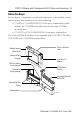
POINT I/O Module with 8 Configurable 24V DC Points and DeviceLogix 5 Before You Begin See the figures to familiarize yourself with major parts of the module, noting that the wiring base assembly is one of the following: • 1734-TB or 1734-TBS POINT I/O two-piece terminal base, which includes the 1734-RTB removable terminal block and 1734-MB mounting base • 1734-TOP or 1734-TOPS POINT I/O one-piece terminal base The 1734-8CFGDLX module is not compatible with 1734-TB3, 1734-TB3S, 1734-TOP3, and 1734-TOP3S ter
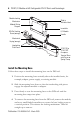
POINT I/O Module with 8 Configurable 24V DC Points and DeviceLogix Module Locking Mechanism Slide-in Writable Label Module Wiring Diagram Insertable I/O Module DIN Rail Locking Screw (orange) Handle Mechanical Keying (orange) Interlocking Side Pieces 44714 1734-TOP or 1734-TOPS One-piece Terminal Base with Screw or Spring Clamp Install the Mounting Base Follow these steps to install the mounting base on the DIN rail. 1.
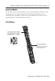
POINT I/O Module with 8 Configurable 24V DC Points and DeviceLogix 7 Install the Module The module can be installed before, or after base installation. Make sure the mounting base is correctly keyed before installing the module into the mounting base. In addition, make sure the mounting base locking screw is positioned horizontal referenced to the base. 1734-TB Base Turn the keyswitch to align the number with the notch. Notch position 1 is shown.
POINT I/O Module with 8 Configurable 24V DC Points and DeviceLogix 1734-TOP Base Be sure the DIN-rail locking screw is in the horizontal position. Turn the keyswitch to align the number with the notch. Notch position 1 is shown. 44710 44228 Follow these steps to install the module. 1. Use a bladed screwdriver to rotate the keyswitch on the mounting base clockwise until the number required for the type of module being installed aligns with the notch in the base. 2.
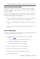
POINT I/O Module with 8 Configurable 24V DC Points and DeviceLogix 9 Install the Removable Terminal Block Read this for information if a removable terminal block (RTB) is supplied with your wiring base assembly, noting that 1734-TOP and 1734-TOPS bases do not have an RTB. To insert the RTB, proceed as follows. Note that if you pull up on the RTB handle to remove the RTB, you can remove and replace the mounting base as necessary without removing any of the wiring. 1.
POINT I/O Module with 8 Configurable 24V DC Points and DeviceLogix Install a 1734-TOPS Base 1. Position the base vertically above the installed units, such as an adapter, power supply, or existing module. 2. Slide the base down, allowing the interlocking side pieces to engage the adjacent installed unit. 3. Press firmly to seat the base on the DIN rail until the base snaps into place. 4. Verify that the DIN-rail locking screw is in a horizontal, locked position before inserting an I/O module.
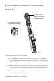
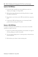
POINT I/O Module with 8 Configurable 24V DC Points and DeviceLogix 11 Wire the Module See the figure and tables for information about how to wire the module.
POINT I/O Module with 8 Configurable 24V DC Points and DeviceLogix Wiring Diagram Prox Prox Prox I/O 0 I/O 1 I/O 2 I/O 3 I/O 4 I/O 5 Prox I/O 6 I/O 7 Load Load Load Load V C C 44687 If a connection to Common or the Supply Voltage is required for two- or three- wire devices, then a 1734-CTM or 1734-VTM can be used. Each I/O point is Input or Output. Channel Terminal Number I/O Common Voltage 0 0 External(1) External(2) 1 1 2 2 3 3 4 4 5 5 6 6 7 7 10/28.
POINT I/O Module with 8 Configurable 24V DC Points and DeviceLogix 13 Configure the Module Read this section for information about how to communicate with your module. I/O messages are sent to (consumed) and received from (produced) the POINT I/O modules. These messages are mapped into the processor’s or scanner’s memory. Each module produces 1, 8 or 20 bytes of input data based on which produced assembly is selected. The default setup is 20 bytes. It consumes 1, 8 or 20 bytes of I/O data (scanner Tx).
POINT I/O Module with 8 Configurable 24V DC Points and DeviceLogix Default Data Map - Produced Assembly Instance 101 (Continued) Message Size: 20 Bytes Data [16] Produce Network Analog Word 6 Data [17] Data [18] Produce Network Analog Word 7 Data [19] Where: • Pt = state of the output point, • PNB = Produce Network Bit, • PM = Peer Missing (each bit represents the presence of a configured peer) • Owned = Owned by a master. When set to 0, the module is producing data without a master.
POINT I/O Module with 8 Configurable 24V DC Points and DeviceLogix 15 Default Data Map - Consumed Assembly Instance 102 Message Size: 20 Bytes Bit 7 6 5 4 3 2 1 0 Data [0] Pt 07 Pt 06 Pt 05 Pt 04 Pt 03 Pt 02 Pt 01 Pt 00 Data [1] CNB 07 CNB 06 CNB 05 CNB 04 CNB 03 CNB 02 CNB 01 CNB 00 Data [2] Reserved Data [3] Data [4] Consume Network Analog Word 0 Data [5] Data [6] Consume Network Analog Word 1 Data [7] Data [8] Consume Network Analog Word 2 Data [9] Data [10] Consume Netw
POINT I/O Module with 8 Configurable 24V DC Points and DeviceLogix You can select other consumed assemblies: • Consumed assembly instance 34 is the first byte of consumed assembly instance 102 (Data [0]). • Consumed assembly instance 112 is the first eight bytes of consumed assembly instance 102 (Data [0]…[7]). In RSLogix5000, the default tags will be: • AdapterName:SlotNumber:O.Data • AdapterName:SlotNumber:O.LogicDefinedData • AdapterName:SlotNumber:O.LogicDefinedIntData[0...
POINT I/O Module with 8 Configurable 24V DC Points and DeviceLogix 17 Data Map - Configuration Assembly Instance 123 (Continued) Message Size: 48 Bytes Data [14] Masterless Produce PIT (ms) Data [15] Data [16] Peer 0 - Slot/MacID Data [17] Peer 0 - Consume Message Length (bytes) Data [18] Peer 0 - EPR (ms) Data [19] Data [20] Peer 1 - Slot/MacID Data [21] Peer 1 - Consume Message Length (bytes) Data [22] Peer 1 - EPR (ms) Data [23] Data [24] Peer 2 - Slot/MacID Data [25] Peer 2 - Consume Me
POINT I/O Module with 8 Configurable 24V DC Points and DeviceLogix Data Map - Configuration Assembly Instance 123 (Continued) Message Size: 48 Bytes Data [38] Peer 5 - EPR (ms) Data [39] Data [40] Peer 6 - Slot/MacID Data [41] Peer 6 - Consume Message Length (bytes) Data [42] Peer 6 - EPR (ms) Data [43] Data [44] Peer 7 - Slot/MacID Data [45] Peer 7 - Consume Message Length (bytes) Data [46] Peer 7 - EPR (ms) Data [47] Where: • Filter = 0 to 65535 μs (1000 = default) • FltM = Fault Mode (0
POINT I/O Module with 8 Configurable 24V DC Points and DeviceLogix 19 Data Map - Configuration Assembly Instance 123 (Continued) Message Size: 48 Bytes • EPR = Expected Packet Rate • PIT = Production Inhibit Time • Slot/MacID = Address of peer Configuration of the 1734-8CFGDLX module must be done through RSNetWorx for DeviceNet.
POINT I/O Module with 8 Configurable 24V DC Points and DeviceLogix Interpret the Indicators See the figure and table that show how to interpret indicators.
POINT I/O Module with 8 Configurable 24V DC Points and DeviceLogix 21 Network Status Status Description Recommended action Off Device is not online. - Device has not completed dup_MAC_id test. - Device not powered - check module status indicator. Apply power to device, wait for dup_MAC_id to complete, and correct, as needed. Green Device is online and has connections in the established state. None. Flashing green Device is online but has no connections in the established state.
POINT I/O Module with 8 Configurable 24V DC Points and DeviceLogix DeviceLogix Status Status Description Recommended action Off DeviceLogix program is not controlling outputs. None. Green DeviceLogix program is controlling outputs. None. Status Description Recommended action Off Input or output is in the OFF state. None. Yellow Input or output is in the ON state. None.
POINT I/O Module with 8 Configurable 24V DC Points and DeviceLogix 23 Specifications Specifications for POINT I/O Module 1734-8CFGDLX DC Input Attribute Value On-state voltage, min 11V DC On-state current, min 2.0 mA On-state current, max 5.0 mA Off-state voltage, max 5V DC Off-state current, min 1.5 mA Input filter Each input independently settable in 1 ms intervals (truncated to 1 ms resolution). Default value is 1000 μs.
POINT I/O Module with 8 Configurable 24V DC Points and DeviceLogix General Specifications Attribute Value Module location 1734-TB, 1734-TBS, 1734-TOP, and 1734-TOPS bases POINTBus current, max 100 mA @ 5V DC Power dissipation, max 2.6 W @ 28.8V DC Thermal dissipation, max 8.9 BTU/hr @ 28.
POINT I/O Module with 8 Configurable 24V DC Points and DeviceLogix 25 Environmental Specifications Attribute Value Temperature, operating IEC 60068-2-1 (Test Ad, Operating Cold), IEC 60068-2-2 (Test Bd, Operating Dry Heat), IEC 60068-2-14 (Test Nb, Operating Thermal Shock): -20…55 °C (-4…131 °F) Temperature, non-operating IEC 60068-2-1 (Test Ab, Unpackaged Non-operating Cold), IEC 60068-2-2 (Test Bb, Unpackaged Non-operating Dry Heat), IEC 60068-2-14 (Test Na, Unpackaged Non-operating Thermal Shock): -
POINT I/O Module with 8 Configurable 24V DC Points and DeviceLogix Environmental Specifications (Continued) Attribute Value EFT/B immunity IEC 61000-4-4: ±3 kV at 5 kHz on signal ports Surge transient immunity IEC 61000-4-5: ±1 kV line-line (DM) and ±2 kV line-earth (CM) on signal ports Conducted RF immunity IEC 61000-4-6: 10V rms with 1 kHz sine-wave 80% AM from 150 kHz…80 MHz Publication 1734-IN039A-EN-P - March 2009
POINT I/O Module with 8 Configurable 24V DC Points and DeviceLogix 27 Certifications Certification (when Value product is marked)(1) CE European Union 2004/108/EC EMC Directive, compliant with: EN 61326-1; Meas./Control/Lab.
Rockwell Automation Support Rockwell Automation provides technical information on the Web to assist you in using its products. At http://support.rockwellautomation.com, you can find technical manuals, a knowledge base of FAQs, technical and application notes, sample code and links to software service packs, and a MySupport feature that you can customize to make the best use of these tools.