Installation Instructions POINT I/O Module with 8 Configurable 24V DC Points Catalog Number 1734-8CFG Topic Page Important User Information 2 Environment and Enclosure 3 Prevent Electrostatic Discharge 4 About the Module 5 Before You Begin 5 Install the Mounting Base 7 Install the I/O Module 8 Install the Removable Terminal Block 10 Remove a Mounting Base 11 Wire the Module 13 Wiring Diagram 14 Configure the Module 15 Interpret the Indicators 17 Specifications 19
POINT I/O Module with 8 Configurable 24V DC Points Important User Information Solid state equipment has operational characteristics differing from those of electromechanical equipment. Safety Guidelines for the Application, Installation and Maintenance of Solid State Controls (Publication SGI-1.1 available from your local Rockwell Automation sales office or online at http://literature.rockwellautomation.
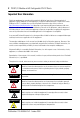
POINT I/O Module with 8 Configurable 24V DC Points 3 Environment and Enclosure ATTENTION This equipment is intended for use in a Pollution Degree 2 industrial environment, in overvoltage Category II applications (as defined in IEC publication 60664-1), at altitudes up to 2000 meters (6562 ft) without derating. This equipment is considered Group 1, Class A industrial equipment according to IEC/CISPR Publication 11.
POINT I/O Module with 8 Configurable 24V DC Points Prevent Electrostatic Discharge ATTENTION ATTENTION ATTENTION This equipment is sensitive to electrostatic discharge, which can cause internal damage and affect normal operation. Follow these guidelines when you handle this equipment. • Touch a grounded object to discharge potential static. • Wear an approved grounding wriststrap. • Do not touch connectors or pins on component boards. • Do not touch circuit components inside the equipment.
POINT I/O Module with 8 Configurable 24V DC Points 5 About the Module The 1734-8CFG module is a 24V DC I/O module with 8 self-configuring points. Each of the I/O points can be a DC input or output. The module supports removal and insertion under power, auto-address, and auto-baud in compliance with the POINTBus backplane.
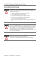
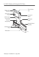
POINT I/O Module with 8 Configurable 24V DC Points Module Locking Mechanism Slide-in Writable Label ule od tus MS ta ork tw s NeStatuE: NO D 4 5 0 6 1 7 2 3 Module Wiring Diagram DIN Rail Locking Screw (orange) Mechanical Keying (orange) Insertable I/O Module RTB Removal Handle Removable Terminal Block (RTB) Interlocking Side Pieces Mounting Base 44713 Publication 1734-IN038A-EN-P - October 2008
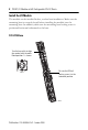
POINT I/O Module with 8 Configurable 24V DC Points 7 Module Locking Mechanism Slide-in Writable Label Module Wiring Diagram Insertable I/O Module DIN Rail Locking Screw (orange) Handle Mechanical Keying (orange) Interlocking Side Pieces 44714 1734-TOP or 1734-TOPS One-piece Terminal Base with Screw or Spring Clamp Install the Mounting Base Follow these steps to install the mounting base on the DIN rail. 1.
POINT I/O Module with 8 Configurable 24V DC Points Install the I/O Module The module can be installed before, or after base installation. Make sure the mounting base is correctly keyed before installing the module into the mounting base. In addition, make sure the mounting base locking screw is positioned horizontal referenced to the base. 1734-TB Base Turn the keyswitch to align the number with the notch. Notch position 1 is shown.
POINT I/O Module with 8 Configurable 24V DC Points 9 1734-TOP Base Be sure the DIN-rail locking screw is in the horizontal position. Turn the keyswitch to align the number with the notch. Notch position 1 is shown. 44710 44228 Follow these steps to install the module. 1. Use a bladed screwdriver to rotate the keyswitch on the mounting base clockwise until the number required for the type of module being installed aligns with the notch in the base. 2.
POINT I/O Module with 8 Configurable 24V DC Points Install the Removable Terminal Block Read this for information if a removable terminal block (RTB) is supplied with your wiring base assembly, noting that 1734-TOP and 1734-TOPS bases do not have an RTB. To insert the RTB, proceed as follows. Note that if you pull up on the RTB handle to remove the RTB, you can remove and replace the mounting base as necessary without removing any of the wiring. 1.
POINT I/O Module with 8 Configurable 24V DC Points 11 Remove a Mounting Base To remove a mounting base, you must first remove any installed module and the module installed in the base to the right. 1. For a module with a two-piece terminal base, use these steps; otherwise, use step 2. a. Remove the removable terminal block (RTB), if wired. b. Unlatch the RTB handle on the I/O module. c. Pull on the RTB handle to remove the RTB. 2. Press on the module lock on the top of the module. 3.
POINT I/O Module with 8 Configurable 24V DC Points Install a 1734-TOPS Base 1. Position the base vertically above the installed units, such as an adapter, power supply, or existing module. 2. Slide the base down, allowing the interlocking side pieces to engage the adjacent installed unit. 3. Press firmly to seat the base on the DIN rail until the base snaps into place. 4. Verify that the DIN-rail locking screw is in a horizontal, locked position before inserting an I/O module.
POINT I/O Module with 8 Configurable 24V DC Points 13 Wire the Module See the figures and tables for information about how to wire the module.
POINT I/O Module with 8 Configurable 24V DC Points Wiring Diagram Prox Prox Prox I/O 0 I/O 1 I/O 2 I/O 3 I/O 4 I/O 5 Prox I/O 6 I/O 7 Load Load Load Load V C C 44687 If a connection to Common or the Supply Voltage is required for two- or three-wire devices, then a 1734-CTM or 1734-VTM can be used. Each I/O point is either Input or Output. Channel Terminal Number I/O Common Voltage 0 0 External(1) External(2) 1 1 2 2 3 3 4 4 5 5 6 6 7 7 10/28.
POINT I/O Module with 8 Configurable 24V DC Points 15 Configure the Module Read this section for information about how to communicate with your module. I/O messages are sent to (consumed) and received from (produced) the POINT I/O modules. These messages are mapped into the processor’s or scanner’s memory. Each module produces 1 byte of input data and consumes 1 byte of I/O data (scanner Tx).
POINT I/O Module with 8 Configurable 24V DC Points Default Data Map - Configuration Assembly Instance 103 Message Size: 8 Bytes 7 Data [0] 6 5 4 3 2 1 0 Group Off2On Input filter Data [1] Data [2] Group On2Off Input filter Data [3] Data [4] FltM 7 FltM 6 FltM 5 FltM 4 FltM 3 FltM 2 FltM 1 FltM 0 Data [5] FltV 7 FltV 6 FltV 5 FltV 4 FltV 3 FltV 2 FltV 1 FltV 0 Data [6] IdlM 7 IdlM 6 IdlM 5 IdlM 4 IdlM 3 IdlM 2 IdlM 1 IdlM 0 Data [7] IdlV 7 IdlV 6 IdlV 5 IdlV 4 Id
POINT I/O Module with 8 Configurable 24V DC Points 17 Interpret the Indicators See the figure and table that show how to interpret indicators. Module Status Module Status Network Status Network Status NODE: NODE: 24Vdc SINK IN SOURCE OUT Status of I/O 0 0 4 Status of I/O 4 Status of I/O 1 1 5 Status of I/O 5 Status of I/O 2 2 6 Status of I/O 6 3 7 Status of I/O 7 Status of I/O 3 1734-8CFG 44688 Indicator State Description Module status Off No power applied to device.
POINT I/O Module with 8 Configurable 24V DC Points Indicator State Description Network status Off Device is not online. - Device has not completed dup_MAC_id test. - Device not powered - check module status indicator. Flashing green Device is online but has no connections in the established state. Green Device is online and has connections in the established state. Flashing red One or more I/O connections in timed-out state. Red Critical link failure - failed communication device.
POINT I/O Module with 8 Configurable 24V DC Points 19 Specifications Specifications for POINT I/O Module 1734-8CFG DC Input Attribute Value On-state voltage, min 11V DC On-state current, min 2.0 mA On-state current, max 5.0 mA Off-state voltage, max 5V DC Off-state current, min 1.5 mA Input filter Each input independently settable in 1 ms intervals (truncated to 1 ms resolution). Default value is 1000 ms.
POINT I/O Module with 8 Configurable 24V DC Points General Specifications Attribute Value Module location 1734-TB, 1734-TBS, 1734-TOP, and 1734-TOPS bases POINTBus current, max 100 mA @ 5V DC Power dissipation, max 2.6 W @ 28.8V DC Thermal dissipation, max 8.9 BTU/hr @ 28.
POINT I/O Module with 8 Configurable 24V DC Points 21 Environmental Specifications Attribute Value Temperature, operating IEC 60068-2-1 (Test Ad, Operating Cold), IEC 60068-2-2 (Test Bd, Operating Dry Heat), IEC 60068-2-14 (Test Nb, Operating Thermal Shock): -20…55 °C (-4…131 °F) Temperature, non-operating IEC 60068-2-1 (Test Ab, Unpackaged Non-operating Cold), IEC 60068-2-2 (Test Bb, Unpackaged Non-operating Dry Heat), IEC 60068-2-14 (Test Na, Unpackaged Non-operating Thermal Shock): -40…85°C (-40…185
POINT I/O Module with 8 Configurable 24V DC Points Environmental Specifications (Continued) Attribute Value EFT/B immunity IEC 61000-4-4: ±3 kV at 5 kHz on signal ports Surge transient immunity IEC 61000-4-5: ±1 kV line-line (DM) and ±2 kV line-earth (CM) on signal ports Conducted RF immunity IEC 61000-4-6: 10V rms with 1 kHz sine-wave 80% AM from 150 kHz…80 MHz Publication 1734-IN038A-EN-P - October 2008
POINT I/O Module with 8 Configurable 24V DC Points 23 Certifications Certification (when Value product is marked)(1) CE European Union 2004/108/EC EMC Directive, compliant with: EN 61326-1; Meas./Control/Lab.
Rockwell Automation Support Rockwell Automation provides technical information on the Web to assist you in using its products. At http://support.rockwellautomation.com, you can find technical manuals, a knowledge base of FAQs, technical and application notes, sample code and links to software service packs, and a MySupport feature that you can customize to make the best use of these tools.