
Installation Instructions Owner manual

10 POINT I/O RS-232 and RS-485 ASCII Modules
Publication
1734-IN588B-EN-P - July 2003
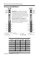
Wiring the 1734-485ASC Module
Module Terminations
Terminal RS-232 RS-485 RS-422
0
Tx
1
S+
1
Tx+
1
1
Rx
2
NC
Rx+
1
2 NC
S-
2
Tx-
2
3 NC NC
Rx-
2
4 NC NC NC
5 NC NC NC
6 NC CG CG
7 SG SG SC
1 S+ and Tx+ are transmit from the module
2 S- and Rx- are receive into the module
NC
NC
NC
SG
S+
S-
NC
CG
Module
Status
Network
Status
S+ = Transmit S- = Receive
CG = Chassis Ground NC = No Connection
SG = Signal Ground
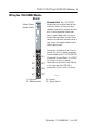
Shielded Cable: The 1734-485ASC module requires
shielded cable to help reduce the effects of electrical
noise coupling. Ground each shield at one end only. A
shield grounded at both ends forms a ground loop, which
can cause module communications to fault. Never connect
a shield to the common side of a logic circuit (this would
introduce noise into the logic circuit).
Connect the shield directly to a chassis ground. This
chassis ground connection is not available on the
1734-485ASC RTB (Removable Terminal Block). On a
POINT I/O system, the chassis ground connection can be
made at the DIN Rail, at the metal panel the DIN Rail is
mounted to, or at the user’s I/O device.
Rx+
Rx-
NC
SG
Tx+
Tx-
NC
CG
Tx = Transmit Rx = Receive
CG = Chassis Ground NC = No Connection
SG = Signal Ground
Module
Status
Network
Status
RS-485
RS-422
4348743487