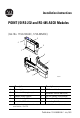
Installation Instructions POINT I/O RS-232 and RS-485 ASCII Modules (Cat. No.
POINT I/O RS-232 and RS-485 ASCII Modules General The ASCII modules provide a flexible DeviceNet interface to a wide variety of RS-232, RS-485, and RS-422 ASCII devices. The modules provide the communication connections to the ASCII device. The 1734-232ASC module connects to the RS-232 network while the 1734-485ASC module connects to the RS-485 or RS-422 network.
POINT I/O RS-232 and RS-485 ASCII Modules 3 Throughout this publication, notes may be used to make you aware of safety considerations.
POINT I/O RS-232 and RS-485 ASCII Modules ATTENTION ! Environment and Enclosure This equipment is intended for use in a Pollution Degree 2 industrial environment, in overvoltage Category II applications (as defined in IEC publication 60664-1), at altitudes up to 2000 meters without derating. This equipment is considered Group 1, Class A industrial equipment according to IEC/CISPR Publication 11.
POINT I/O RS-232 and RS-485 ASCII Modules 5 ATTENTION ! WARNING ! POINT I/O is grounded through the DIN rail to chassis ground. Use zinc-plated, yellow-chromated steel DIN rail to assure proper grounding. Using other DIN rail materials (e.g. aluminum, plastic, etc.) which can corrode, oxidize or are poor conductors, can result in improper or intermittent platform grounding. When you connect or disconnect the Removable Terminal Block (RTB) with field side power applied, an electrical arc can occur.
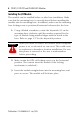
POINT I/O RS-232 and RS-485 ASCII Modules Installing the I/O Module The module can be installed before or after base installation. Make sure that the mounting base is correctly keyed before installing the module into the mounting base. In addition, make sure the mounting base locking screw is positioned horizontal referenced to the base. 1.
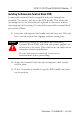
POINT I/O RS-232 and RS-485 ASCII Modules 7 Installing the Removable Terminal Block (RTB) A removable terminal block is supplied with your wiring base assembly. To remove, pull up on the RTB handle. This allows the mounting base to be removed and replaced as necessary without removing any of the wiring. To reinsert the removable terminal block, proceed as follows. 1. Insert the end opposite the handle into the base unit. This end has a curved section that engages with the wiring base.
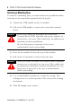
POINT I/O RS-232 and RS-485 ASCII Modules Removing a Mounting Base To remove a mounting base, you must remove any installed module, and remove the removable terminal block (if wired). 1. Unlatch the RTB handle on the I/O module. 2. Pull on the RTB handle to remove the removable terminal block. WARNING ! When you connect or disconnect the Removable Terminal Block (RTB) with field side power applied, an electrical arc can occur. This could cause an explosion in hazardous location installations.
POINT I/O RS-232 and RS-485 ASCII Modules 9 Wiring the 1734-232ASC Module RS-232 Module Status Network Status Shielded Cable: The 1734-232ASC module requires shielded cable to help reduce the effects of electrical noise coupling. Ground each shield at one end only. A shield grounded at both ends forms a ground loop, which can cause module communications to fault. Never connect a shield to the common side of a logic circuit (this would introduce noise into the logic circuit).
POINT I/O RS-232 and RS-485 ASCII Modules Wiring the 1734-485ASC Module RS-485 Module Status Network Status RS-422 Shielded Cable: The 1734-485ASC module requires shielded cable to help reduce the effects of electrical noise coupling. Ground each shield at one end only. A shield grounded at both ends forms a ground loop, which can cause module communications to fault. Never connect a shield to the common side of a logic circuit (this would introduce noise into the logic circuit).
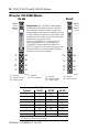
POINT I/O RS-232 and RS-485 ASCII Modules 11 RS-232 1 0 Tx 2 S+ 3 4 2 NC NC 7 6 2 NC CG 43124 Tx, S+ = Transmit NC = No Connection CG = Chassis Ground 3 4 NC 7 Rx+ Tx- 5 NC SG Tx+ 3 4 NC 1 0 NC S- 5 NC RS-422 1 0 Rx NC 6 RS-485 Rx5 NC NC 6 SG 43488 CG 7 SG 43489 Rx, S- = Receive SG = Signal Ground Publication 1734-IN588B-EN-P - July 2003
POINT I/O RS-232 and RS-485 ASCII Modules Communicating with the ASCII Modules The ASCII modules operate as the PointBus front-end to your serial device. Data can be exchanged with the master through a polled, cyclic, or change-of-state connection. Bit-Strobe Command Response Messaging and the Unconnected Message Manager (UCMM) are not supported1.
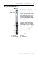
POINT I/O RS-232 and RS-485 ASCII Modules 13 Troubleshooting with the Indicators RS-232 RS-485 Module Status Module Status Module Status Network Status Network Status Network Status NODE: NODE: RS485 / 422 ASCII TxD 1734 232ASC TxD RxD 1734 232ASC RxD 1734 485ASC 43125 Indication 43490 Probable Cause Module Status Off No power applied to device Green Device operating normally Flashing Green Device needs commissioning due to configuration missing, incomplete or incorrect.
POINT I/O RS-232 and RS-485 ASCII Modules Indication Probable Cause Network Status Off Device is not on-line - Device has not completed dup_MAC_id test. - Device not powered - check module status indicator Flashing Green Device is on-line but has no connections in the established state. Green Device on-line and has connections in the established state. Flashing Red One or more I/O connections in timed-out state Red Critical link failure - failed communication device.
POINT I/O RS-232 and RS-485 ASCII Modules 15 Safety Approvals The following information applies when operating this equipment in hazardous locations: Informations sur l’utilisation de cet équipement en environnements dangereux : Products marked “CL I, DIV 2, GP A, B, C, D” are suitable for use in Class I Division 2 Groups A, B, C, D, Hazardous Locations and nonhazardous locations only. Each product is supplied with markings on the rating nameplate indicating the hazardous location temperature code.
POINT I/O RS-232 and RS-485 ASCII Modules WARNING ! EXPLOSION HAZARD · Do not disconnect equipment unless power has been removed or the area is known to be nonhazardous. · Do not disconnect connections to this equipment unless power has been removed or the area is known to be nonhazardous. Secure any external connections that mate to this equipment by using screws, sliding latches, threaded connectors, or other means provided with this product.
POINT I/O RS-232 and RS-485 ASCII Modules 17 Specifications Specifications - 1734-232ASC, -485ASC Modules Number of Inputs 1 full duplex Input Voltage Signal with respect to Signal Ground (SG) "0", Asserted, ON, Space, Active +3 to +25V dc "1", Disasserted, OFF, Mark, -3 to -25V dc Inactive Indicators 1 green/red module status indicator, logic side 1 green/red network status indicator, logic side 2 greed TXD, RXD status indicators, logic side Keyswitch Position 2 (specialty) Module Location 1734-TB
POINT I/O RS-232 and RS-485 ASCII Modules Specifications - 1734-232ASC, -485ASC Modules (Continued) Send (Produce) on DeviceNet to Master Receive String Data Type Array, short_string, string Pad Mode Pad mode disabled, enabled Pad Character ASCII character Receive Swap Mode Disabled, 16-bit, 24-bit, 32-bit swap DeviceNet Handshake Mode Master/slave handshake, produce immediate Produce Assembly Size 4-132 Serial Data 0-128 bytes Receive Transaction ID 0-255 Serial Port Transmit to ASCII De
POINT I/O RS-232 and RS-485 ASCII Modules 19 Specifications - 1734-232ASC, -485ASC Modules (Continued) General Specifications Dimensions Inches (Millimeters) 2.21H x 0.47W x 2.97L (56H x 12W x 75.
POINT I/O RS-232 and RS-485 ASCII Modules Specifications - 1734-232ASC, -485ASC Modules (Continued) Conducted RF Immunity IEC 61000-4-6: 10Vrms with 1kHz sine-wave 80%AM from 150kHz to 80MHz Emissions CISPR 11 Group 1, Class A Enclosure Type Rating None (open-style) Conductors Wire Size 14 AWG (2.5mm2) - 22AWG (0.25mm2) shielded solid or stranded copper wire rated at 75°C or greater 3/64 inch (1.
POINT I/O RS-232 and RS-485 ASCII Modules 21 Notes: Publication 1734-IN588B-EN-P - July 2003
POINT I/O RS-232 and RS-485 ASCII Modules Notes: Publication 1734-IN588B-EN-P - July 2003
POINT I/O RS-232 and RS-485 ASCII Modules 23 Notes: Publication 1734-IN588B-EN-P - July 2003
Rockwell Automation Support Rockwell Automation tests all of our products to ensure that they are fully operational when shipped from the manufacturing facility. If you are experiencing installation or startup problems, please review the troubleshooting information contained in this publication first. If you need technical assistance to get your module up and running, please contact Customer Support (see the table below); our trained technical specialists are available to help.