User Manual 1732E ArmorBlock Dual-Port EtherNet/IP 4-Point Analog Input and Output Modules Catalog Numbers 1732E-IF4M12R, 1732E-OF4M12R
Important User Information Solid-state equipment has operational characteristics differing from those of electromechanical equipment. Safety Guidelines for the Application, Installation and Maintenance of Solid State Controls (publication SGI-1.1 available from your local Rockwell Automation sales office or online at http://www.rockwellautomation.com/literature/) describes some important differences between solid-state equipment and hard-wired electromechanical devices.
Preface Read this preface to familiarize yourself with the rest of the manual. It provides information concerning: • who should use this manual • the purpose of this manual • related documentation • conventions used in this manual Who Should Use this Manual Use this manual if you are responsible for designing, installing, programming, or troubleshooting control systems that use 1732E ArmorBlock Dual Port EtherNet/IP Dual-Port 4-Point Analog Input and Output Modules.
Notes: iv Rockwell Automation Publication 1732E-UM005A-EN-E - July 2012
Table of Contents Preface Who Should Use this Manual . . . . . . . . . . . . . . . . . . . . . . . . . . . . . . . . . . . . . . Purpose of this Manual . . . . . . . . . . . . . . . . . . . . . . . . . . . . . . . . . . . . . . . . . . . . Related Documentation. . . . . . . . . . . . . . . . . . . . . . . . . . . . . . . . . . . . . . . . Common Techniques Used in this Manual . . . . . . . . . . . . . . . . . . . . . . . . . .
Table of Contents Connection Tab . . . . . . . . . . . . . . . . . . . . . . . . . . . . . . . . . . . . . . . . . . . . . . Configuration Tab. . . . . . . . . . . . . . . . . . . . . . . . . . . . . . . . . . . . . . . . . . . . Alarm Configuration Tab . . . . . . . . . . . . . . . . . . . . . . . . . . . . . . . . . . . . . Internet Protocol Tab . . . . . . . . . . . . . . . . . . . . . . . . . . . . . . . . . . . . . . . . Calibration Tab . . . . . . . . . . . . . . . . . . . . . . . . . . . . . . . . .
Table of Contents Chapter 6 Troubleshoot the Modules Interpret Status Indicators . . . . . . . . . . . . . . . . . . . . . . . . . . . . . . . . . . . . . . . . 69 Check for Faults . . . . . . . . . . . . . . . . . . . . . . . . . . . . . . . . . . . . . . . . . . . . . . . . . 70 Appendix A Specifications General Specifications . . . . . . . . . . . . . . . . . . . . . . . . . . . . . . . . . . . . . . . . . . . . Input Specifications . . . . . . . . . . . . . . . . . . . . . . . . . . . . . . . . . .
Table of Contents viii Rockwell Automation Publication 1732E-UM005A-EN-E - July 2012
Chapter 1 Overview of the 1732E ArmorBlock Analog Input and Output Modules Overview Module Features This chapter provides an introduction to the features and functionalities of the 1732E ArmorBlock Analog Input and Output Modules, 1732E-IF4M12R and 1732E-OF4M12R.
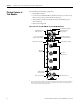
Chapter 1 Overview of the 1732E ArmorBlock Analog Input and Output Modules Physical Features of Your Modules The modules have the following components: • Node address switches • Connectors (two EtherNet/IP D-code M12 connectors, two micro-style Power in/out connectors, four I/O M12 connectors) • Status indicators (Link, I/O, Module, Network, and Auxiliary power status indicators) • Functional earth ground Physical Features of 1732E-IF4M12R and 1732E-OF4M12R Modules Functional Earth Ground(1) EtherNet/IP
Overview of the 1732E ArmorBlock Analog Input and Output Modules Types of Modules Hardware/Software Compatibility Input and Output Types Chapter 1 The Analog Input and Output modules are as follows.
Chapter 1 Overview of the 1732E ArmorBlock Analog Input and Output Modules Process Alarms The following level alarms are available for the for 1732E-IF4M12R module: • Low • Low-Low • High • High-High When the channel input goes below a low alarm or above a high alarm, a bit is set in the data table. All Alarm Status bits can be read individually or by reading the Channel Status Byte (see page 48). You can configure each channel alarm individually.
Overview of the 1732E ArmorBlock Analog Input and Output Modules Chapter 1 Lowest and Highest Signal for Overrange and Underrange Detection Digital Filters Available Range Lowest Signal in Range Highest Signal in Range -10…10 V -10 V 10 V 0…5 V 0V 5V -5…5 V -5 V 5V The 1732E-IF4M12R module also supports a digital filter to smooth input data noise transients on each input channel. This value specifies the time constant for a digital first order lowpass filter on the input.
Chapter 1 Overview of the 1732E ArmorBlock Analog Input and Output Modules Notes: 6 Rockwell Automation Publication 1732E-UM005A-EN-E - July 2012
Chapter 2 Install Your ArmorBlock Module Overview Install the Module This chapter shows you how to install and wire the 1732E ArmorBlock Dual Port 4-Point EtherNet/IP Analog Input and Output modules. The only tools you require are a flat or Phillips head screwdriver and drill.
Chapter 2 Install Your ArmorBlock Module 5. Replace switch dust caps. Make sure not to over tighten. 6. Reapply power. 7. Record IP address on product label found on the side of enclosure. Set Network Address Example shows network switches set at 163, which sets the module IP address to 192.168.1.163. 2 0 4 8 6 2 2 Note: You need to remove the protective switch dust caps before you can adjust the address settings.
Install Your ArmorBlock Module Mount the Module Chapter 2 Two sets of mounting holes are used to mount the module directly to a panel or machine. Mounting holes accommodate #6 (M3) pan head screws. The torque specification is 0.68 Nm (6 lb-in.). To mount the module on a wall or panel, use the screw holes provided in the module. Refer to the drilling dimensions illustration to guide you in mounting the module. Mounting Dimensions 37 (1.46) 16.2 (0.64) Millimeters (Inches) 19.8 (0.
Chapter 2 Install Your ArmorBlock Module Mount the Module in High Vibration Areas If you mount the module in an area that is subject to shock or vibration, we recommend you use a flat and a lock washer to mount the module. Mount the flat and the lock washer as shown in the mounting illustration. Torque the mounting screws to 0.68 Nm (6 lb-in.).
Install Your ArmorBlock Module Chapter 2 Ethernet Connector D-Code Micro Network Female Connector (View into connector 1) Pin 1M12_Tx+ Pin 2 M12_Rx+ Pin 3 M12_TxPin 4 M12_RxPin 5 Connector shell shield GND 5 1 4 2 3 44808 Use the 1585D–M4DC–H: Polyamide small body unshielded mating connectors for the D-Code M12 female network connector. IMPORTANT Note that the distance between the center of each Ethernet connector is 16.2 mm (see Mounting Dimensions on page 9).
Chapter 2 Install Your ArmorBlock Module Both modules require two 24V DC (nominal) supplies. These supplies are called the Module Power and the Auxiliary Power. The Module power supplies the microprocessor and Ethernet portions of the module. The Auxiliary Power provides power for the voltage or current outputs on the 1732E-OF4M12R analog output module. Internally, the Module Power and Auxiliary Power are electrically isolated.
Chapter 3 Configure Your Analog Input and Output Modules with RSLogix 5000 Software Introduction This chapter guides you through the steps required to configure your modules using the RSLogix 5000 software. Note that the modules presented in this chapter can be configured using RSLogix 5000 software, version 20, or later.
Configure Your Analog Input and Output Modules with RSLogix 5000 Software Set Up the Hardware In this example, a ControlLogix chassis contains the Logix5565 processor in slot 1 and a 1756-EN2T bridge module in slot 3. The 1732E ArmorBlock module is mounted remotely. Slot Logix5565 Logix5565 Local Chassis 1732E ArmorBlock Ethernet Module 192.168.1.3 0 1 2 3 Logix5565 Controller (slot 1) EtherNet/IP 1756-EN2T Chapter 3 1732E ArmorBlock Data 1756-EN2T 192.168.1.20 (slot 3) Switch 192.168.1.
Configure Your Analog Input and Output Modules with RSLogix 5000 Software Create the Example Application Chapter 3 Perform the following steps to create the example application: 1. From the File menu, select New. The New Controller dialog opens. 2. Enter an appropriate name for the Controller, for example, ArmorBlock_IO_Controller. 3. Select the correct version, chassis type, and slot number of the controller, and the folder where you want to save the RSLogix 5000 software file (Create In).
Chapter 3 Configure Your Analog Input and Output Modules with RSLogix 5000 Software Configure Your I/O Module You must configure your module upon installation. The module will not work until it has been configured with at least the default configuration. RSLogix 5000 Configuration Software You must use RSLogix 5000, version 20 or later, to configure your module. You have the option of accepting default configuration for your module or writing point-level configuration specific to your application.
Configure Your Analog Input and Output Modules with RSLogix 5000 Software Chapter 3 Add the Local EtherNet/IP Bridge to the I/O Configuration 1. If necessary, go offline. If you are not offline, use this pull-down menu to go offline. 2. Add the EtherNet/IP Bridge to your RSLogix 5000 project. A. Right-click 1756 Backplane. B. Select New Module. 3. Expand Communications and select the new module in the Select Module dialog that appears. Select the 1756-EN2T EtherNet/IP Bridge. A.
Chapter 3 Configure Your Analog Input and Output Modules with RSLogix 5000 Software 4. The New Module dialog opens. Configure the bridge module as illustrated below. A. Name the bridge. B. Enter the IP address. C. Select slot 3 for the EtherNet/IP bridge. D. Make sure the Minor Revision number matches your module revision number. E. Choose an Electronic Keying method. For more information, see page 23. F. Click OK.
Configure Your Analog Input and Output Modules with RSLogix 5000 Software Chapter 3 2. On the Select Module Type dialog that appears, select the 1732E-IF4M12R module. Click Create. To look for the 1732E-IF4M12R module in the list, you can type the catalog number in the search box or use the filters. To do so, click Clear Filters and check Analog in the Module Type Category Filters.
Chapter 3 Configure Your Analog Input and Output Modules with RSLogix 5000 Software 3. The New Module dialog appears. Fill in the Module Properties information as shown, and then click OK. Note that we have used the following properties in this example: Field Name Name IP address Electronic keying Revision Connection Value TEST_1732EIF4M12R 192.168.1.3 Compatible Module 1.
Configure Your Analog Input and Output Modules with RSLogix 5000 Software Download the Program to Your Controller Chapter 3 After you write configuration for your module, the module does not use this configuration until you download it to the owner-controller. The download transfers the entire program to the controller, overwriting any existing program. Download module configuration as shown below: A. Click here to see the pull-down menu. B. Click download.
Chapter 3 Configure Your Analog Input and Output Modules with RSLogix 5000 Software 1. On the I/O Configuration tree for your project in RSLogix 5000, right-click the name of your module. 2. Select Properties. The Module Properties dialog appears and has the following tabs available for configuration. 3. Click any of the tabs to edit the parameters for your module. The next sections show you how to edit the different tabs in the Module Properties dialog. TIP Tabs can be selected in any order.
Configure Your Analog Input and Output Modules with RSLogix 5000 Software Chapter 3 Module Definition Fields Field Name Description Series Specifies the module series. Revision Specifies the module’s major and minor revision. Electronic Keying The electronic keying feature automatically compares the expected module, as shown in the RSLogix 5000 I/O Configuration tree, to the physical module before I/O communication begins.
Chapter 3 Configure Your Analog Input and Output Modules with RSLogix 5000 Software when the controller is in Run mode. The RPI provides a defined, maximum period of time when data is transferred to the owner-controller. 1. Choose from the options on the Connection tab. Connection Tab Fields Field Description Requested Packet Interval (RPI) (ms) A user-defined rate at which the module updates the information sent to its owner-controller.
Configure Your Analog Input and Output Modules with RSLogix 5000 Software Chapter 3 Configuration Tab The Configuration tab on the Module Properties dialog box lets you program information on each of the four channels on the 1732E-IF4M12R module. 1. Choose from the options on the Configuration tab. Configuration tab Field Description Channel Indicates the four input channels 0…3. Input range Input can be voltage or current, with current mode as default.
Chapter 3 Configure Your Analog Input and Output Modules with RSLogix 5000 Software Configuration tab Field Description High Engineering High engineering value helps determine the engineering units the signal values scale into. The high engineering term corresponds to the high signal value. The scaling equation used is shown below. (Signal-LowSignal)(HighEngineering-LowEngineering) + Low Engineering Data = High Signal - Low Signal Low Engineering One of four points used in scaling.
Configure Your Analog Input and Output Modules with RSLogix 5000 Software Chapter 3 Click Channel button to set limits and alarm configuration for each of the 4 channels. Use the sliders to set limits. HH slider sets High High limits; HI sets High limits; LL for Low Low; and LO for Low. 1. Choose from the options on the Alarm Configuration tab.
Chapter 3 Configure Your Analog Input and Output Modules with RSLogix 5000 Software Alarm Configuration tab Field What to do Description Low Low Choose from -32,768...32,767 Select a value so that any value out of range in this field causes a profile validation error. This value also appears in the LL slider on this dialog. Disable All Alarms Click to check the checkbox Check the box to disable all alarms.
Configure Your Analog Input and Output Modules with RSLogix 5000 Software Chapter 3 2. On other fields (Domain Name, Host Name, Primary DNS Server Address, Secondary DNS Server Address), specify the corresponding parameter. Click Set and then click OK. Port Configuration Tab To configure the Ethernet ports, click the Port Configuration tab. This tab is only available for editing when the device is online.
Chapter 3 Configure Your Analog Input and Output Modules with RSLogix 5000 Software Calibration Tab The Calibration tab on the Module Properties dialog box lets you recalibrate the module, if necessary. Calibration corrects any hardware inaccuracies on a particular channel. For detailed information about calibration, see Calibrate Your Modules on page 45.
Configure Your Analog Input and Output Modules with RSLogix 5000 Software Chapter 3 The editing process begins on the main page of RSLogix 5000 software. 1. On the I/O Configuration tree for your project in RSLogix 5000, right-click the name of your module. 2. Select Properties. The Module Properties dialog appears and has the following tabs available for configuration. 3. Click any of the tabs to edit the parameters for your module.
Chapter 3 Configure Your Analog Input and Output Modules with RSLogix 5000 Software You also can edit Module Definition properties such as revision, electronic keying, and data. To do so, click Change. General Tab Field Description Field Name Description Series Specifies the module series. Revision Specifies the module’s major and minor revision.
Configure Your Analog Input and Output Modules with RSLogix 5000 Software Chapter 3 General Tab Field Description Field Name Description Connection Available options are Data and Listen Only, with Data as default. Calibration and Configuration options are not available for Listen Only option. Listen Only specifies a dependent connection where a device receives inputs from the target device, but does not send configuration data with the target device.
Chapter 3 Configure Your Analog Input and Output Modules with RSLogix 5000 Software 2. Do one of the following: • Click Apply to store a change but stay on the dialog box to choose another tab. • Click OK if you are finished making changes.
Configure Your Analog Input and Output Modules with RSLogix 5000 Software Chapter 3 Configuration Tab 1. Choose from the options on the Configuration tab. Configuration tab Field Description Channel Indicates the four input channels 0…3.
Chapter 3 Configure Your Analog Input and Output Modules with RSLogix 5000 Software Configuration tab Field Description High Engineering High engineering value helps determine the engineering units the signal values scale into. The high engineering term corresponds to the high signal value. The scaling equation used is shown below.
Configure Your Analog Input and Output Modules with RSLogix 5000 Software Chapter 3 1. Choose from the options on the Limit Configuration tab. Limit Configuration tab Field What to do Description Channel Select apush button to correspond to a channel (0…3). Refers to the channel being configured. Click to configure. Clamp Limits See Clamping/Limiting on page 47 for more information.
Chapter 3 Configure Your Analog Input and Output Modules with RSLogix 5000 Software Fault/Program Action Tab 1. To configure the Fault/Program Action tab, set the following parameters: Fault/Program Action tab 38 Field What to do Description Channel Select a push button to correspond to a channel (0…3). Refers to the channel being configured.
Configure Your Analog Input and Output Modules with RSLogix 5000 Software Chapter 3 2. Do one of the following: • Click Apply to store a change but stay on the dialog box to choose another tab. • Click OK if you are finished making changes. Internet Protocol Tab 1. To configure your IP settings, click the Internet Protocol tab. This tab is only available for editing when the device is online. To manually configure your IP settings, specify the IP address in the Physical Module IP Address field. 2.
Chapter 3 Configure Your Analog Input and Output Modules with RSLogix 5000 Software Port Configuration Tab To configure the Ethernet ports, click the Port Configuration tab. This tab is only available for editing when the device is online. To configure the ports: To Then Use the default port speed and duplex settings Leave Auto-negotiate port speed and duplex checked. This setting determines the actual speed and duplex setting.
Configure Your Analog Input and Output Modules with RSLogix 5000 Software Chapter 3 particular channel. The Calibration Range that appears on the Calibration tab is dependent on the output range configured for the channel. For detailed information about calibration, see Calibrate Your Modules on page 45.
Chapter 3 Configure Your Analog Input and Output Modules with RSLogix 5000 Software Check the status of your module using these tabs. Chapter Summary 42 This chapter provided instructions on how to configure the 1732E ArmorBlock Analog Input and Output modules through the RSLogix 5000 software.
Chapter 4 Configurable Features for the Analog Input and Output Modules Overview This chapter describes how the different configuration parameters affect the analog input and output channels. It also includes the data structure for both modules.
Chapter 4 Configurable Features for the Analog Input and Output Modules Input Types and Ranges Each of the four 1732E-IF4M12R input points can be configured as either current input or voltage input, with current mode as default configuration.
Configurable Features for the Analog Input and Output Modules Chapter 4 Using a step input change to illustrate the filter response, as shown in the illustration, you can see that when the digital filter time constant elapses, 63.2% of the total response is reached. Each additional time constant achieves 63.2% of the remaining response. 100% 63% Amplitude 0 Unfiltered Input TA = 0.01 sec TA = 0.5 sec TA = 0.99 sec 0 0.01 0.5 0.
Chapter 4 Configurable Features for the Analog Input and Output Modules Real-time Sampling This parameter instructs the module how often to scan its input channels and obtain all available data. The data is produced at the rate configured by the RPI parameter on the connection tab. This feature is applied on a module-wide basis. Process Alarms Process alarms alert you when the module has exceeded configured high or low limits for each channel. You can latch process alarms.
Configurable Features for the Analog Input and Output Modules Chapter 4 The user must do two things to use the output as a current or voltage device: • Wire for the correct output type (see page 10) • Configure accordingly through RSLogix 5000 (see page 35) Current Mode In current mode, the module supports either 0…20 mA or 4…20 mA output currents independently for each channel, with the latter as default output range.
Chapter 4 Configurable Features for the Analog Input and Output Modules outside that range. This safety feature sets a high clamp and a low clamp. Once clamps are determined for a module, any data received from the controller that exceeds those clamps sets an appropriate limit alarm and transitions the output to that limit but not beyond the requested value. For example, an application may set the high clamp on a module for 8V and the low clamp for -8V.
Configurable Features for the Analog Input and Output Modules Chapter 4 1732E-IF4M12R – Configuration Assembly Instance 100 Data Structure Configuration Bit 7 Byte Bit 6 Bit 5 26…27 Channel 1 High Engineering 28…29 Channel 1 Digital Filter 30…31 Channel 1 Low Alarm 32…33 Channel 1 High Alarm 34…35 Channel 1 Low Low Alarm 36…37 Channel 1 High High Alarm 38 Channel 1 Input Range 39 Channel 1 Enable Alarm Latch 40 Channel 1 Disable Alarms 41…43 Reserved (Ignore) 44…45 Channel 2 Low En
Chapter 4 Configurable Features for the Analog Input and Output Modules 1732E-OF4M12R – Configuration Assembly Instance 101 Data Structure Configuration Bit 7 Byte 50 Bit 6 Bit 5 4…5 Channel 0 Fault Value 6…7 Channel 0 Idle Value 8…9 Channel 0 Low Engineering 10…11 Channel 0 High Engineering 12…13 Channel 0 Low Clamp 14…15 Channel 0 High Clamp 16 Channel 0 Output Range 17 Channel 0 Fault Action 18 Channel 0 Idle Action 19 Channel 0 Enable Alarm Latch 20 Channel 0 Disable Alarms 2
Configurable Features for the Analog Input and Output Modules Chapter 4 1732E-OF4M12R – Configuration Assembly Instance 101 Data Structure Configuration Bit 7 Byte Bit 6 Bit 5 64…65 Channel 3 Fault Value 66…67 Channel 3 Idle Value 68…69 Channel 3 Low Engineering 70…71 Channel 3 High Engineering 72…73 Channel 3 Low Clamp 74…75 Channel 3 High Clamp 76 Channel 3 Output Range 77 Channel 3 Fault State 78 Channel 3 Idle State 79 Channel 3 Enable Alarm Latch 80 Channel 3 Disable Alarms 8
Chapter 4 Configurable Features for the Analog Input and Output Modules 1732E-OF4M12R – Produced Assembly Instance 107 Data Structure Produced Byte Bit 7 Bit 6 Bit 5 0…3 Reserved (must be zero) 4 Channel 0 Status(1) 5 Channel 0 Status(1) 6 Channel 0 Status(1) 7 Channel 0 Status(1) Bit 4 Bit 3 Bit 2 Bit 1 Bit 0 (1) This parameter is in Byte and has the following structure: Bit 0 = Fault; Bit 1 = Calibration; Bit 2 = Low Alarm; Bit 3 = High Alarm Chapter Summary 52 This chapter discuss
Chapter 5 Calibrate Your Modules Overview The Analog Input and Output modules are shipped to you calibrated but calibration is also made available through the RSLogix 5000 software should you choose to recalibrate to increase module accuracy for your specific application. This chapter shows you how to calibrate your modules. It includes the following topics.
Chapter 5 Calibrate Your Modules Module Recommended Instrument Range 1732E-IF4M12R -10V…+10V source ±500 μV accuracy 0…20 mA source ±2 μA accuracy 1732E-OF4M12R DMM accurate to within ±500 μV or ±2 μA IMPORTANT Do not calibrate your module with an instrument that is less accurate than those recommended to avoid anomalies. • Calibration appears to occur normally but the module gives inaccurate data during operation. • A calibration fault occurs, forcing you to abort calibration.
Calibrate Your Modules Chapter 5 While you are online, you must access the Calibration tab on the Module Properties dialog box through RSLogix 5000. Follow these steps to calibrate your module. 1. Click Calibration Tab on the Module Properties dialog box. Choose whether to calibrate each channel one at a time or in groups all at once 2. Check the Calibrate checkbox to specify which channel to calibrate. In this example, check Channels 0…3. 3. Under Calibrate Channels select One At a Time. 4.
Chapter 5 Calibrate Your Modules If at least one channel has been selected and there is a mismatch between the device in the RSLogix 5000 I/O Configuration and the actual physical device, another warning dialog comes up. It informs you that this is dangerous with an active system and there is a mismatch. This message box gives you an option to quit. Help is provided to you more information. From the Danger dialog, for a module not currently used for control, click OK to continue. 6.
Calibrate Your Modules Chapter 5 7. Set the calibrator for the high reference voltage and apply it to the module The High Value dialog appears. TIP If several channels have been selected for calibration with One At a Time option enabled, only one channel will appear in the list at the first round of calibration (that is, after low reference and high reference calibration). TIP If calibration is configured to be done In Groups, the High Value dialog box shows all the channels enabled for calibration.
Chapter 5 Calibrate Your Modules Calibrate the Output Module (1732E-OF4M12R) Output calibration is a multi-step process that involves measuring a signal from the module. This section has two parts, as shown in the table. Topic Page Current Meter Calibration 58 Voltage Meter Calibration 61 Current Meter Calibrations RSLogix 5000 software commands the module to output specific levels of current. You must measure the actual level and record the results.
Calibrate Your Modules Chapter 5 4. Click the Calibration Tab on the Module Properties dialog box. 5. Set the channels to be calibrated. In this example, all channels are enabled for calibration. TIP For the output module, calibration is done one channel at a time. 6. Click Start Calibration to access the Calibration Wizard. This button is active when: • the system is online, and • you selected at least one of the channels.
Chapter 5 Calibrate Your Modules If at least one channel has been selected and there is a mismatch between the device in the RSLogix 5000 I/O Configuration and the actual physical device, another warning dialog comes up. It informs you that this is dangerous with an active system and there is a mismatch. This message box gives you an option to quit. Help is provided to you more information. 8. From the Danger dialog, for a module not currently used for control, click OK to continue.
Calibrate Your Modules Chapter 5 • For failed calibration, go to step 13. • For successful calibration, go to step 14 . 13. If the calibration failed, click Retry to recalibrate the same channel. This takes you back to steps 8…12 until you get successful calibration on the channel. 14. If the calibration is successful, click Next to start calibration on the next channel (in this example, channel 1). This takes you back to steps 8…12.
Chapter 5 Calibrate Your Modules 3. At the Output Range, choose the range from the pull-down menu to calibrate the channels. Click Apply. 4. Click the Calibration Tab on the Module Properties dialog box. 5. Set the channels to be calibrated. In this example, all channels are enabled for calibration. TIP For the output module, calibration is done one channel at a time. 6. Click Start Calibration to access the Calibration Wizard.
Calibrate Your Modules Chapter 5 7. After clicking Start Calibration, a warning dialog appears notifying you of the risk involved in calibrating an active system and gives you the option to quit. If at least one channel has been selected and there is a mismatch between the device in the RSLogix 5000 I/O Configuration and the actual physical device, another warning dialog comes up. It informs you that this is dangerous with an active system and there is a mismatch.
Chapter 5 Calibrate Your Modules 12. Click Next to calibrate the module. The Output Calibration Results page appears. • For failed calibration, go to step 13. • For successful calibration, go to step 14 . 13. If the calibration failed, click Retry to recalibrate the same channel. This takes you back to steps 8…12 until you get successful calibration on the channel. 14. If the calibration is successful, click Next to start calibration on the next channel (in this example, channel 1).
Chapter 6 Troubleshoot the Modules This chapter describes the different status indicators available in the analog input and output modules, 1732E-IF4M12R and 1732E-OF4M12R, and how to interpret these indicators to help troubleshoot the modules. It also includes a section on how to check your module for faults through the RSLogix 5000 software.
Chapter 6 Troubleshoot the Modules Indicator Status for Modules Indicator Status Description Module status Off No power applied to the device. Flashing red/ green The module is performing POST (Power-On Self Test), which completes within 30 s. Green Device operating normally. Flashing red Module has experienced a recoverable fault. Red Unrecoverable fault – may require device replacement. Off The device is not initialized or the module does not have an IP address.
Troubleshoot the Modules Chapter 6 • Warning signal on the main screen next to the module – This occurs when the connection to the module is broken. Warning icon appears when a communications fault occurs or if the module is inhibited Warning signal – The module has a communications fault • Message in a screen’s status line.
Chapter 6 Troubleshoot the Modules Notes: 68 Rockwell Automation Publication 1732E-UM005A-EN-E - July 2012
Appendix A Specifications General Specifications The analog input and output modules, 1732E-IF4M12R and 1732E-OF4M12R, have the following general specifications. General Specifications Attributes Value Voltage, power, max 30V DC Voltage, power, min 12V DC Module power 12…30V DC @ @ 150mA – 1732E-IF4M12R 12…30V DC @ @ 250mA – 1732E-OF4M12R Power consumption 3 W @ 24V DC, typical 3.
Appendix A Specifications Input Specifications – 1732E-IF4M12R Attributes Value Input range Current input Voltage input 32 mA, 275 mW ±30V, 20 mA, 25 mW Input impedance 125 kΩ per channel Accuracy 0.1% Full Scale @ 25 °C (77 °F) Accuracy drift with temperature, max 40 ppm % Full Scale /°C @ 25 °C (77 °F) Calibration Factory calibrated. Calibration is also supported through RSLogix 5000.
Specifications Appendix A Environmental Specifications The analog input and output modules, 1732E-IF4M12R and 1732E-OF4M12R, have the following environmental specifications.
Appendix A Specifications Certifications The analog input and output modules, 1732E-IF4M12R and 1732E-OF4M12R, have the following certifications. Certifications Certification (when product is marked)(1) Value c-UR-us UL Recognized Component Industrial Control Equipment, certified for US and Canada. See UL File E322657. CE European Union 2004/108/EC EMC Directive, compliant with: EN 61326-1; Meas./Control/Lab.
Appendix B 1732E ArmorBlock Embedded Web Server Introduction Rockwell Automation offers enhanced 1732E ArmorBlock for your EtherNet/IP control systems so you can monitor data remotely via web pages. This chapter shows how you can use the module’s web server.
Appendix B 1732E ArmorBlock Embedded Web Server Access the Home Page of the Web Server From your web browser, enter the IP address of the 1732E ArmorBlock module. The module displays its home page. Module home page Specify the IP address of the module in the Address field. Log On to the Web Server Many of the features of the 1732E ArmorBlock I/O require you to log on with appropriate access.
1732E ArmorBlock Embedded Web Server Appendix B Navigate the 1732E ArmorBlock I/O You navigate the web server pages by using the navigation panel on the left of the screen. There are also tabs across the top you can use to navigate the sections within folders Tabs across the top match the documents within a folder, as shown in the left navigation panel. Click folders to open and close additional levels of information. Click a document to display a web page showing specific information.
Appendix B 1732E ArmorBlock Embedded Web Server Access Configuration Information You can also view configuration information through the Web Server pages. Click Configuration folder. Click the Configuration folder to expand the navigation. You can view and edit Device Identity, Network Configuration and Device Services information.
Appendix C Module Tag Definitions The 1732E-IF4M12R and 1732E-OF4M12R modules have the following sets of tags: • Configuration • Input • Output (for 1732E-OF4M12R only) Module Tags for 1732E-IF4M12R Input Tags (1732E-IF4M12R) Tag Name Data Type Definition I.Fault DINT Collection of all module level fault bits. I.Ch0Data I.Ch1Data I.Ch2Data I.
Appendix C Module Tag Definitions Input Tags (1732E-IF4M12R) Tag Name Data Type Definition I.Ch0Overrange I.Ch1Overrange I.Ch2Overrange I.Ch3Overrange BOOL Alarms bit indicating the channel’s input is greater than the maximum detectable input signal. Configuration Tags (1732E-IF4M12R) Tag Name Data Type Definition C.Ch0LEngineering C.Ch1LEngineering C.Ch2LEngineering C.Ch3LEngineering INT The low engineering value helps determine the engineering units the signal values scale into.
Module Tag Definitions Appendix C Configuration Tags (1732E-IF4M12R) Tag Name Data Type Definition C.Ch0LimitAlarmLatch C.Ch1LimitAlarmLatch C.Ch2LimitAlarmLatch C.Ch3LimitAlarmLatch SINT Enables latching for the process alarms. Latching causes the process alarms to remain set until an unlatch service is explicitly sent to the channel or alarm. C.Ch0AlarmDisable C.Ch1AlarmDisable C.Ch2AlarmDisable C.
Appendix C Module Tag Definitions Configuration Tags (1732E-OF4M12R) Tag Name Data Type Definition C.Ch0HEngineering C.Ch1HEngineering C.Ch2HEngineering C.Ch3HEngineering INT The high engineering value helps determine the engineering units the signal values scale into. The high engineering term corresponds to the high signal value. The scaling equation used is as follows: (Signal-LowSignal)(HighEngineering-LowEngineering) Data = + Low Engineering High Signal - Low Signal C.Ch0LClamp C.Ch1LClamp C.
Module Tag Definitions Appendix C • edit tags – this option allows you to add or delete tags but not to change their values When you click Edit Tags or Monitor Tags, you can view and/or edit the tags through the following screen that shows all the tags for your modules: Rockwell Automation Publication 1732E-UM005A-EN-E - July 2012 81
Appendix C Module Tag Definitions Notes: 82 Rockwell Automation Publication 1732E-UM005A-EN-E - July 2012
Index Numerics 1585D–M4DC–H 11 1585D-M4TBDM-x 11 1585D-M4TBJM-x 11 1732E ArmorBlock embedded web server 73 navigate 75 1732E-IF4M12R 1, 3, 4, 5 calibration 54 configurable features 43 configuration data 48 Configuration tags 78 digital filters 5 input points 44 input tags 77 overrange and underrange 4 produced data 51 specifications 69 troubleshoot 65 wiring 10 1732E-OF4M12R 1, 3, 12, 20 calibration 58 configurable features 46 configuration data 50 configuration tags 79 consumed data 51 edit configuration 3
Index format 69, 70 module 73 monitor 73 types 21, 30 data tables 48 default configuration 16 use 16 default gateway 8 DHCP 7, 8 diagnostic information 75 digital filters 1, 5, 25, 44 dimensions 69 DNS Server primary 29, 39 secondary 29, 39 domain name 29, 39 Domain Name Server (DNS) 8 dynamic reconfiguration 21, 30 E EFT/B immunity 71 electronic keying 23, 32 choosing in RSLogix 5000 18 compatible module 23, 32 disable keying 23, 32 exact match 23, 32 embedded web server 1732E Armorblock 73 browser requi
Index listen only 23, 33 Logix5565 14 low alarm 27 low engineering 26, 36, 45 low-low alarm 27 LVD 12 M manuals related iii minor revision setting in RSLogix 5000 18 module add new 16 data 73 electronic keying 32 mount 9 power 12 revision 32 series 32 tags 77 Module Definition 20, 22 electronic keying 23 fields 23 revision 23 series 23 Module Properties 22, 31, 36 monitor data 73 monitoring 41 mounting 7, 10 high vibration area 10 module 9 panel 9 wall 9 N network address 7 switches 2, 8 network diagnost
Index output 70 voltage 69 weight 69 wiring category 69 status indicators 2, 65, 69 auxiliary power 2, 65 flashing green 66 flashing red 66 green 66 I/O 2, 65 link 65 module 2, 65 network 2, 65 red 66 surge transient immunity 71 switch value 001 8 888 8 999 8 T tags 21, 30 TCP 8 temperature ambient 71 nonoperating 71 operating 71 torque 9, 10 troubleshoot 65, 66 U UL Type 1 enclosure 12 underrange 1 unicast 24 use default configuration 16 redundancy 15 RSLogix 5000 16 screw holes 9 V vibration 71 voltag
Rockwell Automation Publication 1732E-UM005A-EN-E - July 2012 11
Rockwell Automation Support Rockwell Automation provides technical information on the Web to assist you in using its products. At http://www.rockwellautomation.com/support/, you can find technical manuals, a knowledge base of FAQs, technical and application notes, sample code and links to software service packs, and a MySupport feature that you can customize to make the best use of these tools.