
Manual

68 Rockwell Automation Publication 1732E-UM004A-EN-E - July 2012
Appendix C Module Tag Definitions
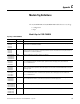
I.CJData INT The cold junction sensor temperature in counts where -32,768 counts is 0 °C (32 °F) and 32,767 counts is 86 °C (186
°F).
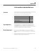
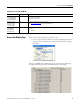
Input Tags (1732E-IT4IM12R)
Tag Name Data Type Definition
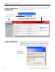
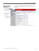
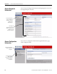
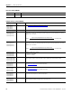
Configuration Tags (1732E-IT4IM12R)
Tag Name Data Type Definition
C.Ch0CJCMode
C.Ch1CJCMode
C.Ch2CJCMode
C.Ch3CJCMode
SINT See Cold Junction Compensation (CJC) Mode on page 39
.
C.CJCModeIndependent SINT See Cold Junction Compensation (CJC) Mode on page 39.
C.Ch0LEngineering
C.Ch1LEngineering
C.Ch2LEngineering
C.Ch3LEngineering
INT One of four points used in scaling. The low engineering helps determine the engineering units the
signal values scale into. The low engineering term corresponds to the low signal value. The scaling
equation used is as follows:
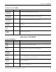
C.Ch0HEngineering
C.Ch1HEngineering
C.Ch2HEngineering
C.Ch3HEngineering
INT One of four points used in scaling. The high engineering helps determine the engineering units the
signal values scale into. The high engineering term corresponds to the high signal value. The scaling
equation used is as follows:
C.Ch0AlarmDisable
C.Ch1AlarmDisable
C.Ch2AlarmDisable
C.Ch3AlarmDisable
SINT Disables all alarms for the channel:
0 - Alarms are not disabled
1 - Alarms are disabled
C.Ch0LimitAlarmLatch
C.Ch1LimitAlarmLatch
C.Ch2LimitAlarmLatch
C.Ch3LimitAlarmLatch
SINT Enables latching for all four process alarms: low, low low, high and high high. Latching causes the
process alarm to remain set until an unlatch service is explicitly sent to the channel or alarm.
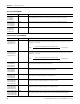
C.Ch0NotchFilter
C.Ch1NotchFilter
C.Ch2NotchFilter
C.Ch3NotchFilter
SINT Configures the channel’s notch filter settings.
See Notch Filter on page 37
for list of valid input values.
C.Ch0SensorType
C.Ch1SensorType
C.Ch2SensorType
C.Ch3SensorType
SINT Configures the channel’s sensor type settings.
See Sensor Type on page 36
for list of valid sensor types.
C.Ch0DigitalFilter
C.Ch1DigitalFilter
C.Ch2DigitalFilter
C.Ch3DigitalFilter
INT A non-zero value enables the filter. The value serves as a time constant in milliseconds that can be
used in a first order lag filter to smooth the input signal.
C.Ch0LAlarmLimit
C.Ch1LAlarmLimit
C.Ch2LAlarmLimit
C.Ch3LAlarmLimit
INT The low alarm trigger point. This value causes the Ch<0...3>LAlarm bit to trigger when the input signal
moves beneath the configured trigger point, in engineering units.
Data =
(Signal-LowSignal)(HighEngineering-LowEngineering)
High Signal - Low Signal
+ Low Engineering
Data =
(Signal-LowSignal)(HighEngineering-LowEngineering)
High Signal - Low Signal
+ Low Engineering