
Manual


44 Rockwell Automation Publication 1732E-UM004A-EN-E - July 2012
Chapter 4 Configurable Features for the Thermocouple and RTD Input Modules
Chapter Summary
This chapter discussed the different configurable features and their effect on all
input channels for both Thermocouple and RTD modules.
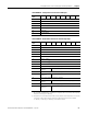
1732E-IR4IM12R – Produced Data Structure for RTD Input
Configuration
Byte
Bit 7 Bit 6 Bit 5 Bit 4 Bit 3 Bit 2 Bit 1 Bit 0
0…3 Reserved (must be zero)
4…5 Channel 0 Data
6…7 Channel 1 Data
8…9 Channel 2 Data
10…11 Channel 3 Data
12 Channel 0 Status
(1)
(1) This parameter is in Byte and has the following structure:
Bit 0 = Fault; Bit 1 = Calibration; Bit 2 = Low Alarm; Bit 3 = High Alarm; Bit 4 = Low Low Alarm; Bit 5 = High High
Alarm; Bit 6 = Underrange; Bit 7 = Overrange
13 Channel 1 Status
(1)
14 Channel 2 Status
(1)
15 Channel 3 Status
(1)