
Manual


Rockwell Automation Publication 1732E-UM004A-EN-E - July 2012 41
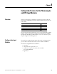
Configurable Features for the Thermocouple and RTD Input Modules Chapter 4
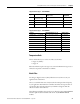
62 Channel 2 Notch Filter
63 Channel 2 Thermocouple Type
64…65 Channel 2 Digital Filter
66…67 Channel 2 Low Alarm
68…69 Channel 2 High Alarm
70…71 Channel 2 Low Low Alarm
72…73 Channel 2 High High Alarm
74 Channel 2 Temperature Units
75 Channel 2 Cold Junction Enable
76…77 Channel 2 Cold Junction Offset
78…79 Reserved (Ignore)
80…81 Channel 3 Low Engineering
82…83 Channel 3 High Engineering
84 Channel 3 Disable Alarms
85 Channel 3 Enable Alarm Latch
86 Channel 3 Notch Filter
87 Channel 3 Thermocouple Type
88…89 Channel 3 Digital Filter
90…91 Channel 3 Low Alarm
92…93 Channel 3 High Alarm
94…95 Channel 3 Low Low Alarm
96…97 Channel 3 High High Alarm
98 Channel 3 Temperature Units
99 Channel 3 Cold Junction Enable
100…101 Channel 3 Cold Junction Offset
(1) Cold Junction Compensation Mode values are:
0 = None, 1 = Channel 1, 2 = Channel 2, 3 = Channel 3, 4 = Channel 4, 5 = Average of all channels with
thermistor attached.
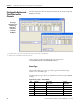
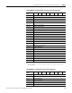
1732E-IR4IM12R – Configuration Data Structure for RTD Input
Configuration
Byte
Bit 7 Bit 6 Bit 5 Bit 4 Bit 3 Bit 2 Bit 1 Bit 0
4…5 Channel 0 Low Engineering
6…7 Channel 0 High Engineering
8…9 Channel 0 Digital Filter
10…11 Channel 0 Low Alarm
12…13 Channel 0 High Alarm
14…15 Channel 0 Low Low Alarm
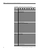
1732E-IT4IM12R – Configuration Data Structure for Thermocouple Input
Configuration
Byte
Bit 7 Bit 6 Bit 5 Bit 4 Bit 3 Bit 2 Bit 1 Bit 0