
Manual

Rockwell Automation Publication 1732E-UM004A-EN-E - July 2012 27
Configure Your Thermocouple and RTD Input Modules with RSLogix 5000 Software Chapter 3
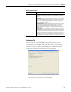
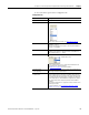
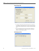
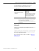
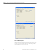
1. Choose from the options on the Configuration tab.
Configuration tab
Field Description
Channel Indicates the four input channels 0…3.
Sensor Type Specifies the sensor type for each channel.
To learn more about sensor types, see Sensor Type
on page 36.
Units Refers to the temperature unit that will be used.
Available in °C and °F.
When the Thermocouple sensor type is set to mV, the temperature
unit field is not available.
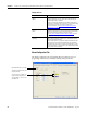
Digital Filter Choose a value in milliseconds that specifies the time constant for a
digital first order lag filter on the input. A value of 0 disables the
filter. Valid filter range is 1…10000.
Notch Filter
Use the default (60 Hz) or choose a frequency that attenuates the
input signal at this specified frequency.
See Notch Filter on page 37 for more information.
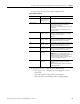
High Engineering
Low Engineering
High Engineering and Low Engineering values are determined by the
Sensor Type selected for each channel.
Enable Cold Junction
Compensation
This parameter enables or disables the use of the external cold
junction compensation for the channel. If enabled, the proper cold
junction compensation value is applied to the selected thermocouple
as determined by the external thermistor. If disabled, the data (cold
junction temperature) is still available but not applied to the input. A
cold junction value can be added using the Cold Junction Offset
parameter.
Cold Junction Compensation is supported on all four channels of the
thermocouple module.
For more information, see Cold Junction Compensation (1732E-
IT4IM12R only) on page 38.
Default value: 60 Hz