User Manual 1732E ArmorBlock Dual-Port EtherNet/IP 4-Point Isolated Thermocouple and RTD Input Modules Catalog Numbers 1732E-IT4IM12R, 1732E-IR4IM12R
Important User Information Solid-state equipment has operational characteristics differing from those of electromechanical equipment. Safety Guidelines for the Application, Installation and Maintenance of Solid State Controls (publication SGI-1.1 available from your local Rockwell Automation sales office or online at http://www.rockwellautomation.com/literature/) describes some important differences between solid-state equipment and hard-wired electromechanical devices.
Preface Read this preface to familiarize yourself with the rest of the manual. It provides information concerning: • who should use this manual • the purpose of this manual • related documentation • conventions used in this manual Who Should Use this Manual Use this manual if you are responsible for designing, installing, programming, or troubleshooting control systems that 1732E ArmorBlock™ EtherNet/IP Dual Port 4-Point Thermocouple and RTD Modules.
Notes: iv Rockwell Automation Publication 1732E-UM004A-EN-E - July 2012
Table of Contents Preface Who Should Use this Manual . . . . . . . . . . . . . . . . . . . . . . . . . . . . . . . . . . . . . . Purpose of this Manual . . . . . . . . . . . . . . . . . . . . . . . . . . . . . . . . . . . . . . . . . . . . Related Documentation. . . . . . . . . . . . . . . . . . . . . . . . . . . . . . . . . . . . . . . . Common Techniques Used in this Manual . . . . . . . . . . . . . . . . . . . . . . . . . . iii iii iii iii Chapter 1 Overview of the 1732E Overview . . . . . . . . . . .
Table of Contents Edit Your Module Configuration . . . . . . . . . . . . . . . . . . . . . . . . . . . . . . . . . . General Tab . . . . . . . . . . . . . . . . . . . . . . . . . . . . . . . . . . . . . . . . . . . . . . . . . . Connection Tab . . . . . . . . . . . . . . . . . . . . . . . . . . . . . . . . . . . . . . . . . . . . . . Configuration Tab for 1732E-IR4IM12R . . . . . . . . . . . . . . . . . . . . . . Configuration Tab for 1732E-IT4IM12R . . . . . . . . . . . . . . . . . . . . . .
Table of Contents Appendix B 1732E ArmorBlock Embedded Web Server Introduction. . . . . . . . . . . . . . . . . . . . . . . . . . . . . . . . . . . . . . . . . . . . . . . . . . . . . Typical Applications . . . . . . . . . . . . . . . . . . . . . . . . . . . . . . . . . . . . . . . . . . . . . Browser Requirements. . . . . . . . . . . . . . . . . . . . . . . . . . . . . . . . . . . . . . . . . . . . Access the Home Page of the Web Server. . . . . . . . . . . . . . . . . . . . . . . . . . .
Table of Contents Notes: viii Rockwell Automation Publication 1732E-UM004A-EN-E - July 2012
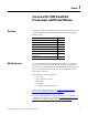
Chapter 1 Overview of the 1732E ArmorBlock Thermocouple and RTD Input Modules Overview Module Features This chapter provides an introduction to the features and functionalities of the 1732E ArmorBlock Thermocouple and RTD Input Modules. It includes the following sections.
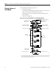
Chapter 1 Overview of the 1732E ArmorBlock Thermocouple and RTD Input Modules Physical Features of Your Module The modules have the following components: • Node address switches • Connectors (two EtherNet/IP D-code M12 connectors, two micro-style Power in/out connectors, four I/O M12 connectors) • Status indicators (Link, I/O, Module, Network, and Auxiliary power status indicators) • Functional earth ground Physical Features of 1732E-IT4IM12R and 1732E-IR4IM12R Modules Functional Earth Ground(1) EtherNet
Overview of the 1732E ArmorBlock Thermocouple and RTD Input Modules Types of Modules Hardware/Software Compatibility Thermocouple Types Chapter 1 The Thermocouple and RTD modules are as follows.
Chapter 1 Overview of the 1732E ArmorBlock Thermocouple and RTD Input Modules • Enter an estimated temperature (Cold Junction Compensation Offset). • Use external cold junction compensators to measure the cold junction temperature directly. To compensate for cold junction temperature voltage, the 1732E-IT4IM12R Thermocouple module has to determine actual cold junction temperature.
Overview of the 1732E ArmorBlock Thermocouple and RTD Input Modules Chapter 1 It supports 3-wire and 2-wire RTDs using a jumper in the wiring at the input connector of the module. The following RTD input types are supported. Supported RTD Types RTD type Temperature Range °C (°F) Voltage Range 100 Ω Pt 385 0…390.48 Ω -200…850 °C (-328…1562 °F) 0…150 mV 200 Ω Pt 385 0…781 Ω -200…650 °C (-328…1202 °F) 0…300 mV 100 Ω Pt 3916 0…337.03 Ω -200…630 °C (-328…1166 °F) 0…156.
Chapter 1 Overview of the 1732E ArmorBlock Thermocouple and RTD Input Modules resistance (10 Ω) range value, or below the minimum range of the thermocouple or RTD. Level Alarms The following level alarms are available. • Low • Low-Low • High • High-High When the channel input goes below a low alarm or above a high alarm, a bit is set in the data table. All Alarm Status bits can be read individually or by reading the Channel Status Byte (see page 35). You can configure each channel alarm individually.
Chapter 2 Install Your ArmorBlock Module Overview Install the Module This chapter shows you how to install and wire the 1732E ArmorBlock EtherNet/IP Dual Port 4-Point Thermocouple and RTD Input modules. The only tools you require are a flat or Phillips head screwdriver and drill.
Chapter 2 Install Your ArmorBlock Module 5. Replace switch dust caps. Make sure not to over tighten. 6. Reapply power. 7. Record IP address on product label found on the side of enclosure. Set Network Address 2 Example shows network switches set at 163, which sets the module IP address to 192.168.1.163. 0 4 8 6 2 2 4 Note: You need to remove the protective switch dust caps before you can adjust the address settings.
Install Your ArmorBlock Module Mount the Module Chapter 2 To mount the module on a wall or panel, use the screw holes provided in the module. Refer to the drilling dimensions illustration to guide you in mounting the module. Mounting Dimensions 37 (1.46) 16.2 (0.64) Millimeters (Inches) 19.8 (0.78) Functional Earth Grounds the I/O block EtherNet/IP communication circuitry which is designed to mitigate the effect of noise on the network.
Chapter 2 Install Your ArmorBlock Module and the lock washer as shown in the mounting illustration. Torque the mounting screws to 0.68 Nm (6 lb-in.). High Vibration Area Mounting Lock washer Flat washer 45768 Wire the Module The 1732E-IT4IM12R and 1732E-IR4IM12R modules have 5-pin micro-style M12 I/O connectors. We provide caps to cover the unused connectors on your module. Connect the quick-disconnect cord sets you selected for your module to the appropriate ports.
Install Your ArmorBlock Module Chapter 2 Ethernet Connector D-Code Micro Network Female Connector 5 1 4 2 3 44808 (View into connector 1) Pin 1 M12_Tx+ Pin 2 M12_Rx+ Pin 3 M12_TxPin 4 M12_RxPin 5 Connector shell shield GND Use the 1585D–M4DC–H: Polyamide small body unshielded mating connectors for the D-Code M12 female network connector. IMPORTANT Note that the distance between the center of each Ethernet connector is 16.2 mm (see Mounting Dimensions on page 9).
Chapter 2 Install Your ArmorBlock Module Both modules require two 24V DC (nominal) supplies. These supplies are called the Module Power and the Auxiliary Power. The Module power supplies the microprocessor and Ethernet portions of the module, while Auxiliary power supplies the I/O circuits. Internally, the Module Power and Auxiliary Power are electrically isolated. IMPORTANT The maximum current that any pin on the power connectors can carry is 4 A.
Chapter 3 Configure Your Thermocouple and RTD Input Modules with RSLogix 5000 Software Introduction This chapter guides you through the steps required to configure your modules using the RSLogix 5000 software. Note that the modules presented in this chapter can be configured using RSLogix 5000 software, version 20, or later.
Configure Your Thermocouple and RTD Input Modules with RSLogix 5000 Software Set Up the Hardware In this example, a ControlLogix chassis contains the Logix5565 processor in slot 1 and a 1756-EN2T bridge module in slot 3. The 1732E ArmorBlock module is mounted remotely. Slot Logix5565 Logix5565 Local Chassis 1732E ArmorBlock Ethernet Module 192.168.1.3 0 1 2 3 Logix5565 Controller (slot 1) EtherNet/IP 1756-EN2T Chapter 3 1732E ArmorBlock Data 1756-EN2T 192.168.1.20 (slot 3) Switch 192.168.1.
Configure Your Thermocouple and RTD Input Modules with RSLogix 5000 Software Create the Example Application Chapter 3 Perform the following steps to create the example application: 1. From the File menu, select New. The New Controller dialog opens. 2. Enter an appropriate name for the Controller, for example, ArmorBlock_IO_Controller. 3. Select the correct version, chassis type, and slot number of the controller, and the folder where you want to save the RSLogix 5000 software file (Create In).
Chapter 3 Configure Your Thermocouple and RTD Input Modules with RSLogix 5000 Software Configure Your I/O Module You must configure your module upon installation. The module will not work until it has been configured with at least the default configuration. RSLogix 5000 Configuration Software You must use RSLogix 5000, version 20 or later, to configure your module. You have the option of accepting default configuration for your module or writing point-level configuration specific to your application.
Configure Your Thermocouple and RTD Input Modules with RSLogix 5000 Software Chapter 3 Add the Local EtherNet/IP Bridge to the I/O Configuration 1. If necessary, go offline. If you are not offline, use this pull-down menu to go offline. 2. Add the EtherNet/IP Bridge to your RSLogix 5000 project. A. Right-click 1756 Backplane. B. Select New Module. 3. Expand Communications and select the new module in the Select Module dialog that appears. Select the 1756-EN2T EtherNet/IP Bridge. A.
Chapter 3 Configure Your Thermocouple and RTD Input Modules with RSLogix 5000 Software 4. The New Module dialog opens. Configure the bridge module as illustrated below. A. Name the bridge. B. Enter the IP address. C. Select slot 3 for the EtherNet/IP bridge. D. Make sure the Minor Revision number matches your module revision number. E. Choose an Electronic Keying method. For more information, see page 22. F. Click OK.
Configure Your Thermocouple and RTD Input Modules with RSLogix 5000 Software Chapter 3 2. On the Select Module Type dialog that appears, select the 1732E-IT4IM12R module. Click Create. To look for the 1732E-IT4IM12R module in the list, you can type the catalog number in the search box or use the filters. To do so, click Clear Filters and check Analog in the Module Type Category Filters.
Chapter 3 Configure Your Thermocouple and RTD Input Modules with RSLogix 5000 Software Note that we have used the following properties in this example: Field Name Name IP address Electronic keying Revision Connection Value TEST_1732EIT4IM12R 192.168.1.3 Compatible Module 1.1 Input Only To add the 1732E-IR4IM12R RTD module, follow the same steps.
Configure Your Thermocouple and RTD Input Modules with RSLogix 5000 Software Edit Your Module Configuration Chapter 3 RSLogix 5000 programming software automatically creates module-defined data types and tags when a module is created. This section describes how to modify the default configuration for input modules. Data types symbolically name module configuration, input and output data. Tags let you provide each a unique name, such as where the user-defined data type and slot reside on the controller.
Chapter 3 Configure Your Thermocouple and RTD Input Modules with RSLogix 5000 Software General Tab The General tab allows you to edit general properties such as Name, IP Address, and Description for your module. You also can edit Module Definition properties such as revision, electronic keying, and data. To do so, click Change. Module Definition Fields Field Name Description Series Specifies the module series. Revision Specifies the module’s major and minor revision.
Configure Your Thermocouple and RTD Input Modules with RSLogix 5000 Software Chapter 3 Module Definition Fields Field Name Description Connection Available options are Data, Input Only, Exclusive Owner, and Listen Only. Calibration and Configuration options are not available for Listen Only option. Input Only specifies an independent connection where a device receives inputs from the target device and sends configuration data to the target device.
Chapter 3 Configure Your Thermocouple and RTD Input Modules with RSLogix 5000 Software Connection Tab Fields Field Description Requested Packet Interval (RPI) (ms) A user-defined rate at which the module updates the information sent to its owner-controller. This interval defines the slowest rate at which a module sends its data to the owner-controller. The time ranges from 2.0…750 ms and is sent to the module with all other configuration parameters.
Configure Your Thermocouple and RTD Input Modules with RSLogix 5000 Software Chapter 3 1. Choose from the options on the Configuration tab. Configuration tab Field Description Channel Indicates the four input channels 0…3. Sensor Type Specifies the sensor type for each channel. To learn more about sensor types, see Sensor Type on page 36. Units Refers to the temperature unit that will be used. Available in °C and °F.
Chapter 3 Configure Your Thermocouple and RTD Input Modules with RSLogix 5000 Software High Engineering and Low Engineering Values for 1732E-IR4IM12R RTD Sensor Type Units Low Engineering High Engineering 200 Ω Pt 385 °C -2000 6300 °F -3280 11660 °C -2000 6500 °F -3280 12020 °C -2000 6500 °F -3280 12020 °C -1000 2600 °F -1480 5000 °C -800 2600 °F -1120 5000 °C -600 1800 °F -760 3560 °C -900 1400 °F -1300 2840 100 Ω Pt 3916 200 Ω Pt 3916 10 Ω Cu 427 120 Ω Ni 6
Configure Your Thermocouple and RTD Input Modules with RSLogix 5000 Software Chapter 3 1. Choose from the options on the Configuration tab. Configuration tab Field Description Channel Indicates the four input channels 0…3. Sensor Type Specifies the sensor type for each channel. To learn more about sensor types, see Sensor Type on page 36. Units Refers to the temperature unit that will be used. Available in °C and °F.
Chapter 3 Configure Your Thermocouple and RTD Input Modules with RSLogix 5000 Software Configuration tab Field Description Cold Junction Compensation Offset Cold Junction Compensation Offset lets you manually enter a cold junction temperature. This can only be done if the external cold junction compensation is disabled. If there is no thermistor available, and the ambient temperature is known to be, for example, 28.00 °C (82.
Configure Your Thermocouple and RTD Input Modules with RSLogix 5000 Software Chapter 3 1. Choose from the options on the Alarm Configuration tab. Alarm Configuration tab Field What to do Description Channel Select a push button to correspond to a channel (0…3) Click the channel that is being configured. Process Alarms Type a value for each of the four alarm trigger points that alert you when the module has exceeded these limitations.
Chapter 3 Configure Your Thermocouple and RTD Input Modules with RSLogix 5000 Software Internet Protocol Tab 1. To configure your IP settings, click the Internet Protocol tab. This tab is only available for editing when the device is online. To manually configure your IP settings, specify the IP address in the Physical Module IP Address field. 2. On the other fields (Domain Name, Host Name, Primary DNS Server Address, Secondary DNS Server Address), specify the corresponding parameter.
Configure Your Thermocouple and RTD Input Modules with RSLogix 5000 Software Chapter 3 To configure the Ethernet ports, click the Port Configuration tab. This tab is only available for editing when the device is online. To configure the ports: To Then Use the default port speed and duplex settings Leave Auto-negotiate port speed and duplex checked. This setting determines the actual speed and duplex setting. Manually configure your port’s speed and duplex settings Follow these steps. 1.
Chapter 3 Configure Your Thermocouple and RTD Input Modules with RSLogix 5000 Software Status and Monitoring Tabs Although each dialog box maintains importance during online monitoring, some of the tabs, such as the Module Info and Network, are blank during the initial module configuration.
Configure Your Thermocouple and RTD Input Modules with RSLogix 5000 Software Chapter 3 Check the status of your module using these tabs. Chapter Summary This chapter provided instructions on how to configure the 1732E ArmorBlock Thermocouple and RTD modules through the RSLogix 5000 software.
Chapter 3 Configure Your Thermocouple and RTD Input Modules with RSLogix 5000 Software Notes: 34 Rockwell Automation Publication 1732E-UM004A-EN-E - July 2012
Chapter 4 Configurable Features for the Thermocouple and RTD Input Modules Overview This chapter describes how the different configuration parameters affect the Thermocouple and RTD input channels. It also includes the data structure for both modules. Topic Page Configure Your Input Modules 36 Configurable Options and Their Effect on the Channels 36 Data Tables 39 Chapter Summary 44 The parameters discussed in this chapter can be set through the RSLogix 5000 software.
Chapter 4 Configurable Features for the Thermocouple and RTD Input Modules Configurable Options and Their Effect on the Channels The following features affect the four input channels for the Thermocouple and RTD Input modules. Sensor Type Temperature Units Digital Filter Notch Filter(1) CJC Enable(2) CJC Offset(2) CJC Mode(2) (1) Notch Filter can be set per channel on the Thermocouple module, and module-wide on the RTD module. (2) Available on the 1732E-IT4IM12R Thermocouple module only.
Configurable Features for the Thermocouple and RTD Input Modules Chapter 4 Supported Sensor Types – 1732E-IT4IM12R Type Material Temperature Range °C (°F) Voltage Range (mV) N Ni/14.2%Cr/1.4%Si vs. Ni/4.4%Si/0.1%Mg -270…1300 °C (-454…2372 °F) -4.345…47.513 R Pt/13%Rh vs. Pt -50…1768 °C (-58…3214.4 °F) -0.226…21.101 S Pt/10%Rh vs. Pt -50…1768 °C (-58…3214.4 °F) -0.236…18.693 T Cu vs. Cu/Ni -270…400 °C (-454…752 °F) -6.258…20.
Chapter 4 Configurable Features for the Thermocouple and RTD Input Modules • • • • 50 Hz 60 Hz (default) 250 Hz 500 Hz Digital Filter A digital filter can be configured for each of the four channels for both Thermocouple and RTD modules based on a configurable time constant set by the user. The time constant value can be configured up to 10,000 ms. A value of 0 disables the filter and is the default value.
Configurable Features for the Thermocouple and RTD Input Modules Chapter 4 channels. Typically, this option should always be enabled except for systems that have no thermoelectric effect, such as test equipment in a controlled lab. When this parameter is set for a channel, compensation is derived from one or more thermistors attached to the module. If not set (disabled), compensation will come from a user-entered value (CJC Offset).
Chapter 4 Configurable Features for the Thermocouple and RTD Input Modules 1732E-IT4IM12R – Configuration Data Structure for Thermocouple Input Configuration Bit 7 Byte 40 Bit 6 Bit 5 Bit 4 Bit 3 4 Cold Junction Mode(1) 5…7 Reserved (Ignore) 8…9 Channel 0 Low Engineering 10…11 Channel 0 High Engineering 12 Channel 0 Disable Alarms 13 Channel 0 Enable Alarm Latch 14 Channel 0 Notch Filter 15 Channel 0 Thermocouple Type 16…17 Channel 0 Digital Filter 18…19 Channel 0 Low Alarm 20…21
Configurable Features for the Thermocouple and RTD Input Modules Chapter 4 1732E-IT4IM12R – Configuration Data Structure for Thermocouple Input Configuration Bit 7 Byte Bit 6 Bit 5 62 Channel 2 Notch Filter 63 Channel 2 Thermocouple Type 64…65 Channel 2 Digital Filter 66…67 Channel 2 Low Alarm 68…69 Channel 2 High Alarm 70…71 Channel 2 Low Low Alarm 72…73 Channel 2 High High Alarm 74 Channel 2 Temperature Units 75 Channel 2 Cold Junction Enable 76…77 Channel 2 Cold Junction Offset 7
Chapter 4 Configurable Features for the Thermocouple and RTD Input Modules 1732E-IR4IM12R – Configuration Data Structure for RTD Input Configuration Bit 7 Byte 42 Bit 6 Bit 5 16…17 Channel 0 High High Alarm 18 Channel 0 Enable Alarm Latch 19 Channel 0 Disable Alarms 20 Channel 0 RTD Type 21 Channel 0 Temperature Scale 22…23 Reserved (Ignore) 24…25 Channel 1 Low Engineering 26…27 Channel 1 High Engineering 28…29 Channel 1 Digital Filter 30…31 Channel 1 Low Alarm 32…33 Channel 1 Hig
Configurable Features for the Thermocouple and RTD Input Modules Chapter 4 1732E-IR4IM12R – Configuration Data Structure for RTD Input Configuration Bit 7 Byte Bit 6 Bit 5 78 Channel 3 Enable Alarm Latch 79 Channel 3 Disable Alarms 80 Channel 3 RTD Type 81 Channel 3 Temperature Scale 82…83 Reserved (Ignore) 84 Notch Filter 85 Reserved (Ignore) Bit 4 Bit 3 Bit 2 Bit 1 Bit 0 1732E-IT4IM12R – Produced Data Structure for Thermocouple Input Configuration Bit 7 Byte Bit 6 Bit 5 Bit 4 B
Chapter 4 Configurable Features for the Thermocouple and RTD Input Modules 1732E-IR4IM12R – Produced Data Structure for RTD Input Configuration Bit 7 Byte Bit 6 Bit 5 0…3 Reserved (must be zero) 4…5 Channel 0 Data 6…7 Channel 1 Data 8…9 Channel 2 Data 10…11 Channel 3 Data 12 Channel 0 Status(1) 13 Channel 1 Status(1) 14 Channel 2 Status(1) 15 Channel 3 Status(1) Bit 4 Bit 3 Bit 2 Bit 1 Bit 0 (1) This parameter is in Byte and has the following structure: Bit 0 = Fault; Bit 1 = Cal
Chapter 5 Calibrate Your Modules Overview The Thermocouple and RTD modules are shipped to you calibrated but calibration is also made available through the RSLogix 5000 software should you choose to recalibrate your module to increase accuracy for your specific application. This chapter shows you how to calibrate your modules through the RSLogix 5000 software. It includes the following topics.
Chapter 5 Calibrate Your Modules Calibrate the Thermocouple Module The 1732E-IT4IM12R module only calibrates in millivolts. You can calibrate the module to a 0…78.125 mV range. IMPORTANT Apply power to the power supply and module for at least 10 minutes before calibrating the module. Perform the calibration process through the RSLogix 5000 software. While you are online, you must access the Calibration tab on the Module Properties dialog box. 1.
Calibrate Your Modules Chapter 5 6. After clicking Start Calibration, a warning dialog appears notifying you of the risk involved in calibrating an active system and gives you the option to quit. If at least one channel has been selected and there is a mismatch between the device in the RSLogix 5000 I/O Configuration and the actual physical device, another warning dialog comes up. It informs you that this is dangerous with an active system and there is a mismatch.
Chapter 5 Calibrate Your Modules 8. Set the calibrator for the high reference voltage and apply it to the module The Input Calibration - High Value dialog appears. TIP If several channels have been selected for calibration with One At a Time option enabled, only one channel will appear in the list at the first round (low reference and high reference) of calibration. TIP If calibration is configured to be done In Groups, the High Value dialog box shows all the channels enabled for calibration. 9.
Calibrate Your Modules Calibrate the RTD Module Chapter 5 The 1732E-IR4IM12R does not calibrate for voltage or current. It uses two precision resistors to calibrate the channels in ohms.
Chapter 5 Calibrate Your Modules Note that you can press the F1 button on your keyboard or click Help from the wizard and warning message that appear to get detailed information about the procedures for calibration. 5. After clicking Start Calibration, a warning dialog appears notifying you of the risk involved in calibrating an active system and gives you the option to quit.
Calibrate Your Modules Chapter 5 7. Set the calibrator for the high reference voltage and apply it to the module The High Value dialog appears. TIP If several channels have been selected for calibration with One At a Time option enabled, only one channel will appear in the list at the first round (low reference and high reference) of calibration. TIP If calibration is configured to be done In Groups, the High Value dialog box shows all the channels enabled for calibration. 8.
Chapter 5 Calibrate Your Modules Notes: 52 Rockwell Automation Publication 1732E-UM004A-EN-E - July 2012
Chapter 6 Troubleshoot the Module This chapter describes the different status indicators available in the 1732E-IT4IM12R and 1732E-IR4IM12R modules and how to interpret these indicators to help troubleshoot the modules. It also includes a section on how to check your module for faults through the RSLogix 5000 software.
Chapter 6 Troubleshoot the Module Indicator Status for the Modules Indicator Status Description Module status Off No power applied to the device. Flashing red/ green The module is performing POST (Power-On Self Test), which completes within 30 s. Green Device operating normally. Flashing red Module has experienced a recoverable fault. Possible minor faults include the following: • IP Address switches do not match configuration in use.
Troubleshoot the Module Chapter 6 • Warning signal on the main screen next to the module – This occurs when the connection to the module is broken. Warning icon appears when a communications fault occurs or if the module is inhibited Warning signal – The module has a communications fault • Message in a screen’s status line.
Chapter 6 Troubleshoot the Module Notes: 56 Rockwell Automation Publication 1732E-UM004A-EN-E - July 2012
Appendix A Specifications General Specifications The 1732E ArmorBlock Thermocouple and RTD Input Modules have the following general specifications. General Specifications Attributes Value Voltage, power, max 30V DC Voltage, power, min 12V DC Module power 12…30V DC @ 300 mA Power consumption 3 W @ 24V DC, typical 3.
Appendix A Specifications Input Specifications – 1732E-IT4IM12R Attributes Value Thermocouple types Type Material Temperature Range °C (°F) Voltage Range (mV) B Pt /30% Rh vs. Pt/ 5% Rh 40…1820 (104…3308) 0…13.820 C W/5% Re vs. W/ 26% Re 0…2320 (32…4208) 0…37.107 E Ni/Cr vs. Cu/Ni -270…1000 (-454…1832) -9.835…76.373 J Ni/Cr vs. Cu/Ni -210…1200 (-346…2192) -8.095…69.553 K Ni/Cr vs. Ni/Al -270…1372 (-454…2501.6) -6.458…54.886 N Ni/14.2%Cr/1.4%Si vs. Ni/4.4%Si/ 0.
Specifications Appendix A Input Specifications – 1732E-IR4IM12R Attributes Value Data format 16-bit sign magnitude Sensors supported 100…200 Ω α =0.00385/0.003916 Pt RTD 100/120 Ω Ni RTD 10 Ω Cu α =0.00427 RTD Sensor Types 100 Ω Pt 385 200 Ω Pt 385 100 Ω Pt 3916 200 Ω Pt 3916 10 Ω Cu 427 120 Ω Ni 672 100 Ω Ni 618 120 Ω Ni 618 Input range RTD type Temperature Range (°C) Voltage Range 100 Ω Pt 385 0…390.48 Ω -200…850 °C 0…156.25 mV 200 Ω Pt 385 0…781 Ω -200…850 °C 0…312.
Appendix A Specifications Environmental Specifications The 1732E ArmorBlock Thermocouple and RTD Input Modules have the following environmental specifications.
Specifications Appendix A Certifications Certification (when product is marked)(1) Value c-UR-us UL Recognized Component Industrial Control Equipment, certified for US and Canada. See UL File E322657. CE European Union 2004/108/EC EMC Directive, compliant with: EN 61326-1; Meas./Control/Lab.
Appendix A Specifications Notes: 62 Rockwell Automation Publication 1732E-UM004A-EN-E - July 2012
Appendix B 1732E ArmorBlock Embedded Web Server Introduction Rockwell Automation offers enhanced 1732E ArmorBlock for your EtherNet/IP control systems so you can monitor data remotely via web pages. This chapter shows how you can use the module’s web server.
Appendix B 1732E ArmorBlock Embedded Web Server Access the Home Page of the Web Server From your web browser, enter the IP address of the 1732E ArmorBlock module. The module displays its home page. Specify the IP address of the module in the Address field. Module home page Log On to the Web Server Many of the features of the 1732E ArmorBlock I/O require you to log on with appropriate access.
1732E ArmorBlock Embedded Web Server Appendix B Navigate the 1732E ArmorBlock I/O You navigate the web server pages by using the navigation panel on the left of the screen. There are also tabs across the top you can use to navigate the sections within folders. Tabs across the top match the documents within a folder, as shown in the left navigation panel. Click folders to open and close additional levels of information. Click a document to display a web page showing specific information.
Appendix B 1732E ArmorBlock Embedded Web Server Access Diagnostic Information You can view specific diagnostic information by clicking Diagnostic Overview on the navigational panel on the left. Click the Diagnostics folder to expand the navigation, then click the Diagnostic Overview page. View diagnostic information such as Ring Status, System Resource Utilization, and CIP Connection Statistics. Access Configuration Information You can also view configuration information through the Web Server pages.
Appendix C Module Tag Definitions The 1732E-IT4IM12R and 1732E-IR4IM12R modules have two sets of tags: • Configuration • Input Module Tags for 1732E-IT4IM12R Input Tags (1732E-IT4IM12R) Tag Name Data Type Definition I.Fault DINT Collection of all module level fault bits I.Ch0Data I.Ch1Data I.Ch2Data I.Ch3Data INT The channel input signal represented in counts where -32,768 counts is the minimum detectable input signal and 32,767 counts is the maximum detectable. I.Ch0Fault I.Ch1Fault I.
Appendix C Module Tag Definitions Input Tags (1732E-IT4IM12R) Tag Name Data Type Definition I.CJData INT The cold junction sensor temperature in counts where -32,768 counts is 0 °C (32 °F) and 32,767 counts is 86 °C (186 °F). Configuration Tags (1732E-IT4IM12R) Tag Name Data Type Definition C.Ch0CJCMode C.Ch1CJCMode C.Ch2CJCMode C.Ch3CJCMode SINT See Cold Junction Compensation (CJC) Mode on page 39. C.CJCModeIndependent SINT See Cold Junction Compensation (CJC) Mode on page 39. C.
Module Tag Definitions Appendix C Configuration Tags (1732E-IT4IM12R) Tag Name Data Type Definition C.Ch0HAlarmLimit C.Ch1HAlarmLimit C.Ch2HAlarmLimit C.Ch3HAlarmLimit INT The high alarm trigger point. This value causes the Ch<0...3>HAlarm bit to trigger when the input signal moves above the configured trigger point, in engineering units. C.Ch0LLAlarmLimit C.Ch1LLAlarmLimit C.Ch2LLAlarmLimit C.Ch3LLAlarmLimit INT The low low alarm trigger point. This value causes the Ch<0...
Appendix C Module Tag Definitions Input Tags (1732E-IR4IM12R) Tag Name Data Type Definition I.Ch0HHAlarm I.Ch0HHAlarm I.Ch0HHAlarm I.Ch0HHAlarm BOOL High high alarm bit that sets when the input signal moves above the configured high high alarm trigger point, Ch0HHAlarmLimit. Remains set until the input signal moves below the trigger point. I.Ch0Underrange I.Ch1Underrange I.Ch1Underrange I.Ch1Underrange BOOL Alarm bits indicating the channel’s input is less than the minimum detectable input signal.
Module Tag Definitions Appendix C Configuration Tags (1732E-IR4IM12R) Tag Name Data Type Definition C.Ch0AlarmDisable C.Ch1AlarmDisable C.Ch2AlarmDisable C.Ch3AlarmDisable SINT Disables all alarms for the channel: 0 - Alarms are not disabled 1 - Alarms are disabled C.Ch0SensorType C.Ch1SensorType C.Ch2SensorType C.Ch3SensorType SINT Configures the channel’s sensor type settings. See Sensor Type on page 36 for list of valid input values.
Appendix C Module Tag Definitions Notes: 72 Rockwell Automation Publication 1732E-UM004A-EN-E - July 2012
Index Numerics 1732E ArmorBlock embedded web server 63 navigate 65 1732E-IR4IM12R 1 configurable features 36 configuration 24 configuration data 41 connectors 3 I/O Configuration 16 input specifications 58 input tags 69 RTD sensor types 4 supported sensor types 37 troubleshooting 53 wiring 10 1732E-IT4IM12R 1 configurable features 36 configuration 26 configuration data 40 configuration tags 68 connectors 3 I/O Configuration 16 input tags 67 produced data 43 supported sensor types 36 supported thermocouples
Index digital filters 6, 35, 25, 27, 38 dimensions 57 DNS Server Address primary 30 secondary 30 domain name 30 dynamic reconfiguration 21 hardware/software compatibility 3 high alarms 6 high engineering 25, 27 high vibration 9 high-high alarms 6, 5 home page web server 64 host name 30 E EFT/B immunity 60 electronic keying 22 choosing in RSLogix 5000 18 compatible module 22 disable keying 22 exact match 22 embedded web server 1732E Armorblock 63 browser requirements 63 emissions 60 enclosure type rating
Index M manuals related iii millivolt 5 minor revision setting in RSLogix 5000 18 module data 63 LED 8 mount 9 power 11, 57 properties 21 revision 22 series 22 tags 67 monitoring 63 mounting 9 dimensions 9 module 9 N network address 7 LED 8 node address switches 2 noise transients 6 normal mode rejection rate 58, 59 notch filter 25, 27, 37 O open-wire detection 5 overrange detection 1, 5 P pan head screws 9 PELV 12 physical features 2 port configuration 30 port speed configure 31 power connectors 11 con
Index thermistor 39 thermistors 4 thermocouple types 3 Thermometrics DC95F302V/W 58 Thermometrics MF65F302V/W 58 torque 10 troubleshooting 53, 54 troubleshoot module 54 U UL Type 1 enclosure 12 underrange detection 1, 5 use default configuration 16 redundancy 15 RSLogix 5000 16 screw holes 9 V vibration 9, 60 W web server 63, 64 home page 64 log in 64 wiring 10 76 Rockwell Automation Publication 1732E-UM004A-EN-E - July 2012
Rockwell Automation Publication 1732E-UM004A-EN-E - July 2012 77
Rockwell Automation Support Rockwell Automation provides technical information on the Web to assist you in using its products. At http://www.rockwellautomation.com/support/, you can find technical manuals, a knowledge base of FAQs, technical and application notes, sample code and links to software service packs, and a MySupport feature that you can customize to make the best use of these tools.