
supporting Sequence of Events
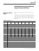

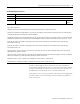

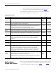
Table Of Contents
- 1732E-UM002A-EN-E 1732E EtherNet/IP ArmorBlock Supporting Sequence of Events User Manual
- Important User Information
- Table of Contents
- Preface
- Chapter 1 - About 1732E ArmorBlock Modules
- Chapter 2 - Module Overview
- Chapter 3 - Use the Module in an ArmorBlock System
- Chapter 4 - Install Your Module
- Chapter 5 - Configure the Module for Your EtherNet/IP Network
- Chapter 6 - Configure the Module Using RSLogix 5000
- Introduction
- Set Up the Hardware
- Create the Example Application
- Configure Your I/O Module
- Overview of the Configuration Process
- Add a New Bridge and Module to Your RSLogix 5000 Project
- Use the Default Configuration
- Change the Default Configuration
- Download Your Configuration
- Edit Your Configuration
- Access Module Data in RSLogix 5000
- Configure RSLogix 5000 and the 1756-EN2T Communication Module for CIP Sync
- Chapter Summary and What’s Next
- Chapter 7 - Module Features
- Introduction
- Determine Module Compatibility
- Module Features That Can Be Configured
- Chapter Summary and What’s Next
- Chapter 8 - Using the Module
- Chapter 9 - Interpret Status Indicators
- Chapter 10 - Troubleshoot the Module
- Appendix A - ArmorBlock 2 Port Ethernet Module Specifications
- Appendix B - Module Tags
- Appendix C - 1732E EtherNet/IP ArmorBlock Supporting Sequence of Events Data Tables
- Appendix D - Connect to Networks via Ethernet Interface
- Appendix E - 1732E ArmorBlock I/O Embedded Web Server
- Glossary
- Index
- How Are We Doing?
- Back Cover

Publication 1732E-UM002A-EN-P - March 2010
1732E EtherNet/IP ArmorBlock Supporting Sequence of Events Data Tables 87
Configuration Assembly Instance 110
16 Input / Status / CIP Sync
Byte Bit 7 Bit 6 Bit 5 Bit 4 Bit 3 Bit 2 Bit 1 Bit 0
0 Reserved CRN
1 Reserved
2 Reserved
3 Reserved
4 Group 0 Input OFF_ON Delay Filter (Low Byte)
5 Group 0 Input OFF_ON Delay Filter (High Byte)
6 Group 0 Input ON_OFF Delay Filter (Low Byte)
7 Group 0 Input ON_OFF Delay Filter (High Byte)
8 Enable IN
OW 7
Enable IN
OW 6
Enable IN
OW 5
Enable IN
OW 4
Enable IN
OW 3
Enable IN
OW 2
Enable IN
OW 1
Enable IN
OW 0
9 Master Sync
Enable
Latch
Events
10 Capture
OffOn 7
Capture
OffOn 6
Capture
OffOn 5
Capture
OffOn 4
Capture
OffOn 3
Capture
OffOn 2
Capture
OffOn 1
Capture
OffOn 0
11 Capture
OffOn 15
Capture
OffOn 14
Capture
OffOn 13
Capture
OffOn 12
Capture
OffOn 11
Capture
OffOn 10
Capture
OffOn 9
Capture
OffOn 8
12 Capture
OnOff 7
Capture
OnOff 6
Capture
OnOff 5
Capture
OnOff 4
Capture
OnOff 3
Capture
OnOff 2
Capture
OnOff 1
Capture
OnOff 0
13 Capture
OnOff 15
Capture
OnOff 14
Capture
OnOff 13
Capture
OnOff 12
Capture
OnOff 11
Capture
OnOff 10
Capture
OnOff 9
Capture
OnOff 8
Where CRN = Configuration Revision Number, Value is 0 after power-on reset and after completely closing the connection. Value is
1 when the module is configured. Once a module is configured, the only way to change its configuration is to close the
connections to it or use the override value of 0.
Enable IN OW x = Enable Input Open Wire x
1 = Enable; 0 = Off
LatchEvents: When set, latches events which means that an event will not be overwritten until acknowledged. For example,
this means that an input’s sequence of events of Off, On, Off, On will cause the first Off to On transition to be recorded, and
the final Off to On transition to be ignored. All subsequent transitions on that point will be ignored until
acknowledged/reset. If the bit is not set, the new Off to On transition will overwrite the first Off to On transition event
immediately, even if the controller has yet to extract that data.
MasterSyncEnable: This is a PTP enable bit which will indicate if the module is expected to sync to a master clock. If not
enabled (0), then the module Status Indicator does not flash green if it is not synchronized to a master clock. Disabling the
bit does not prevent the module from synchronizing to a master clock.
CaptureOffOn: Enables capturing Off to On events on a per point basis. If cleared, that point will not record Off to On events.
This is useful for not reporting events that are not necessary.
CaptureOnOff: Enables capturing On to Off events on a per point basis. If cleared, that point will not record On to Off events.
This is useful for not reporting events that are not necessary.
Input Filter values = 0, 1000, 2000, 4000, 8000 or 16000 µs.