
supporting Sequence of Events
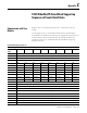

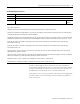
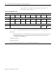

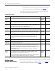
Table Of Contents
- 1732E-UM002A-EN-E 1732E EtherNet/IP ArmorBlock Supporting Sequence of Events User Manual
- Important User Information
- Table of Contents
- Preface
- Chapter 1 - About 1732E ArmorBlock Modules
- Chapter 2 - Module Overview
- Chapter 3 - Use the Module in an ArmorBlock System
- Chapter 4 - Install Your Module
- Chapter 5 - Configure the Module for Your EtherNet/IP Network
- Chapter 6 - Configure the Module Using RSLogix 5000
- Introduction
- Set Up the Hardware
- Create the Example Application
- Configure Your I/O Module
- Overview of the Configuration Process
- Add a New Bridge and Module to Your RSLogix 5000 Project
- Use the Default Configuration
- Change the Default Configuration
- Download Your Configuration
- Edit Your Configuration
- Access Module Data in RSLogix 5000
- Configure RSLogix 5000 and the 1756-EN2T Communication Module for CIP Sync
- Chapter Summary and What’s Next
- Chapter 7 - Module Features
- Introduction
- Determine Module Compatibility
- Module Features That Can Be Configured
- Chapter Summary and What’s Next
- Chapter 8 - Using the Module
- Chapter 9 - Interpret Status Indicators
- Chapter 10 - Troubleshoot the Module
- Appendix A - ArmorBlock 2 Port Ethernet Module Specifications
- Appendix B - Module Tags
- Appendix C - 1732E EtherNet/IP ArmorBlock Supporting Sequence of Events Data Tables
- Appendix D - Connect to Networks via Ethernet Interface
- Appendix E - 1732E ArmorBlock I/O Embedded Web Server
- Glossary
- Index
- How Are We Doing?
- Back Cover
Publication 1732E-UM002A-EN-P - March 2010
1732E EtherNet/IP ArmorBlock Supporting Sequence of Events Data Tables 85
In order to acknowledge receipt of an event the user must transition the
corresponding NewDataAck bit from 0 to 1 and set the EventAck to indicate
whether to acknowledge the Off-On or On-Off transition for the input. the
NewDataAck bits and EventAck are in consumed assembly 139.
Timestamps are zero at power-up and after a timestamp is acknowledged. The
time base and epoch of the timestamps are determined by the grandmaster
clock of the system.
272-279 IN 14 On-Off Time Stamp (64 bit)
280-287 IN 15 Off-On Time Stamp (64 bit)
288-295 IN 15 On-Off Time Stamp (64 bit)
296 Reserved Synced to
Master
Where: INOW = Input Open Wire
INSC = Input Short Circuit
NewData = New data, has been detected upon that input and an unread event is queued for that point.
EventOV = Set whenever the module begins to lose events for that input pint. Events may be lost when new events are either ignored or
overwriting existing events which have yet to be acknowledged.
EventNumber = Running count of events which increments by one each new event. Allows the controller to check for a new event easily by
comparing this number to the last retrieved event. If the EventNumber reaches its maximum value and rolls over it rolls over to 1, not 0.
Inx Off-On Time Stamp = Timestamp corresponding to when an event was recorded at one of the module’s inputs when the input
transitioned from Off to On.
Inx On-Off Time Stamp = Timestamp corresponding to when an event was recorded at one of the module’s inputs when the input
transitioned from On to Off.
Local Clock Offset = The offset from the local clock to the system time. This value is useful for detecting steps in time. This value will
update when a PTP update is received.
Offset Time Stamp = The time when the PTP message was received that caused the Local Clock Offset to update. This value is initially zero
and the first timestamp occurs when the module synchronizes with the master clock.
Grandmaster Clock ID = The I. D. number of the Grandmaster clock the module is synchronized to.
Synced to Master = 1 indicates the module is synchronized with a master clock. 0 indicates it is not.
Produced Assembly Instance 118