
supporting Sequence of Events


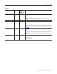
Table Of Contents
- 1732E-UM002A-EN-E 1732E EtherNet/IP ArmorBlock Supporting Sequence of Events User Manual
- Important User Information
- Table of Contents
- Preface
- Chapter 1 - About 1732E ArmorBlock Modules
- Chapter 2 - Module Overview
- Chapter 3 - Use the Module in an ArmorBlock System
- Chapter 4 - Install Your Module
- Chapter 5 - Configure the Module for Your EtherNet/IP Network
- Chapter 6 - Configure the Module Using RSLogix 5000
- Introduction
- Set Up the Hardware
- Create the Example Application
- Configure Your I/O Module
- Overview of the Configuration Process
- Add a New Bridge and Module to Your RSLogix 5000 Project
- Use the Default Configuration
- Change the Default Configuration
- Download Your Configuration
- Edit Your Configuration
- Access Module Data in RSLogix 5000
- Configure RSLogix 5000 and the 1756-EN2T Communication Module for CIP Sync
- Chapter Summary and What’s Next
- Chapter 7 - Module Features
- Introduction
- Determine Module Compatibility
- Module Features That Can Be Configured
- Chapter Summary and What’s Next
- Chapter 8 - Using the Module
- Chapter 9 - Interpret Status Indicators
- Chapter 10 - Troubleshoot the Module
- Appendix A - ArmorBlock 2 Port Ethernet Module Specifications
- Appendix B - Module Tags
- Appendix C - 1732E EtherNet/IP ArmorBlock Supporting Sequence of Events Data Tables
- Appendix D - Connect to Networks via Ethernet Interface
- Appendix E - 1732E ArmorBlock I/O Embedded Web Server
- Glossary
- Index
- How Are We Doing?
- Back Cover
Publication 1732E-UM002A-EN-P - March 2010
78 Module Tags
Tags Used
Configuration Tags
The following table describes the configuration tags generated in
RSLogix 5000 when you use your module.
Configuration Tags
Tag Name Type Description
C.FilterOffOn INT Sets the OFF to ON filter time for all 16 inputs. Times are set in μs increments of 0,
1000 (default), 2000, 4000, 8000 and 16000 μs.
0 = no filtering
For more information on Software Configurable Input Filters, see page 46
.
C.FilterOnOff INT Sets the ON to OFF filter time for all 16 inputs. Times are set in μs increments of 0, 1000
(default), 2000, 4000, 8000 and 16000 μs.
0 = no filtering
For more information on Software Configurable Input Filters, see page 46
.
C.PointXX_YYOpenWireEn BOOL XX = even numbered input 0…14
YY = odd numbered input 1…15
OpenWire is enabled or disabled per I/O connector. For example, 00_01 or 14_15
0 = Off (default)
1 = Enable Open Wire
C.LatchEvents BOOL Latches events so that an event will not be overwritten until acknowledged.
0 = SOE not latched
1 = SOE latched (default)
Latched means that a sequence of events of LO to HI and HI to LO then LO to HI will cause
the first LO to HI transition to be recorded and the final LO to HI to be ignored. All
subsequent transitions on that point will be ignored until acknowledged/reset. If the bit is
not set, the new LO to HI will overwrite the first LO to HI event immediately, even if the
controller has yet to extract that data.
C.MasterSyncEn BOOL PTP enabled bit indicates if the module is expected to sync to a master clock.
0 = Synchronization indication disabled (default)
1 = Synchronization indication enabled
If not enabled (0) then the Module Status Indicators will not flash green if we are not
sync'd to a master clock. Disabling the bit does not prevent the module from
synchronizing to a master clock.