
supporting Sequence of Events
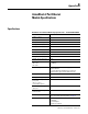
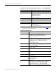
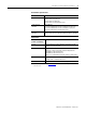

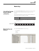

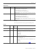
Table Of Contents
- 1732E-UM002A-EN-E 1732E EtherNet/IP ArmorBlock Supporting Sequence of Events User Manual
- Important User Information
- Table of Contents
- Preface
- Chapter 1 - About 1732E ArmorBlock Modules
- Chapter 2 - Module Overview
- Chapter 3 - Use the Module in an ArmorBlock System
- Chapter 4 - Install Your Module
- Chapter 5 - Configure the Module for Your EtherNet/IP Network
- Chapter 6 - Configure the Module Using RSLogix 5000
- Introduction
- Set Up the Hardware
- Create the Example Application
- Configure Your I/O Module
- Overview of the Configuration Process
- Add a New Bridge and Module to Your RSLogix 5000 Project
- Use the Default Configuration
- Change the Default Configuration
- Download Your Configuration
- Edit Your Configuration
- Access Module Data in RSLogix 5000
- Configure RSLogix 5000 and the 1756-EN2T Communication Module for CIP Sync
- Chapter Summary and What’s Next
- Chapter 7 - Module Features
- Introduction
- Determine Module Compatibility
- Module Features That Can Be Configured
- Chapter Summary and What’s Next
- Chapter 8 - Using the Module
- Chapter 9 - Interpret Status Indicators
- Chapter 10 - Troubleshoot the Module
- Appendix A - ArmorBlock 2 Port Ethernet Module Specifications
- Appendix B - Module Tags
- Appendix C - 1732E EtherNet/IP ArmorBlock Supporting Sequence of Events Data Tables
- Appendix D - Connect to Networks via Ethernet Interface
- Appendix E - 1732E ArmorBlock I/O Embedded Web Server
- Glossary
- Index
- How Are We Doing?
- Back Cover

73 Publication 1732E-UM002A-EN-P - March 2010
Appendix
A
ArmorBlock 2 Port Ethernet
Module Specifications
Specifications
ArmorBlock 2 Port Ethernet Module Input Specifications – 1732E-IB16M12SOEDR
Attributes Value
Number of inputs 16
Input type Sink, 24V DC
Voltage, off-state input, max 5V DC
Voltage, on-state input, max 30V DC
Voltage, on-state input, nom 24V DC
Voltage, on-state input, min 11V DC
Current, off-state input, max 1.5 mA @ 5V DC
Current, on-state input, max 5 mA @ 30V DC
Voltage, sensor source, max 30V DC
Voltage, sensor source, min 10V DC
Input delay time
ON to OFF
OFF to ON
0…16000 μs
Isolation voltage 50V (continuous), Basic Insulation Type, Inputs and Sensor
Power to Network
No isolation between individual Inputs or between
Network channels Type tested at 707V DC for 60s
Voltage, auxiliary power, max 30V DC
Voltage, auxiliary power, min 12V DC
Current, Ethernet system
power, max
(pins 2, 3 sensor
source/module power)
1.2 A
Current, sensor source, per
input, max
50 mA
Current, sensor source, per
connector, max
100 mA
Timestamp accuracy 100 μs
Refer to the module input delay tables on page 68
.
Communication rate EtherNet/IP
10/100 Mbps
Full or half-duplex
100 meter per segment