
supporting Sequence of Events
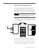
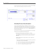
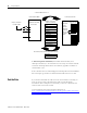
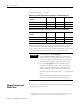
Table Of Contents
- 1732E-UM002A-EN-E 1732E EtherNet/IP ArmorBlock Supporting Sequence of Events User Manual
- Important User Information
- Table of Contents
- Preface
- Chapter 1 - About 1732E ArmorBlock Modules
- Chapter 2 - Module Overview
- Chapter 3 - Use the Module in an ArmorBlock System
- Chapter 4 - Install Your Module
- Chapter 5 - Configure the Module for Your EtherNet/IP Network
- Chapter 6 - Configure the Module Using RSLogix 5000
- Introduction
- Set Up the Hardware
- Create the Example Application
- Configure Your I/O Module
- Overview of the Configuration Process
- Add a New Bridge and Module to Your RSLogix 5000 Project
- Use the Default Configuration
- Change the Default Configuration
- Download Your Configuration
- Edit Your Configuration
- Access Module Data in RSLogix 5000
- Configure RSLogix 5000 and the 1756-EN2T Communication Module for CIP Sync
- Chapter Summary and What’s Next
- Chapter 7 - Module Features
- Introduction
- Determine Module Compatibility
- Module Features That Can Be Configured
- Chapter Summary and What’s Next
- Chapter 8 - Using the Module
- Chapter 9 - Interpret Status Indicators
- Chapter 10 - Troubleshoot the Module
- Appendix A - ArmorBlock 2 Port Ethernet Module Specifications
- Appendix B - Module Tags
- Appendix C - 1732E EtherNet/IP ArmorBlock Supporting Sequence of Events Data Tables
- Appendix D - Connect to Networks via Ethernet Interface
- Appendix E - 1732E ArmorBlock I/O Embedded Web Server
- Glossary
- Index
- How Are We Doing?
- Back Cover

Publication 1732E-UM002A-EN-P - March 2010
68 Using the Module
Timestamp Accuracy = +/- 40 µs.
(1)
Maximum input frequency (for each input) = 250 Hz 50% duty cycle. The
module can provide unique timestamps for input transitions on separate
inputs as long as they occur 25 µs apart. An input that changes state less than
25 µs after another input may receive the timestamp of the first input.
Chapter Summary and
What’s Next
In this chapter, you learned how to use the module. The next chapter describes
interpreting the Status Indicators.
Module Input Pin OFF->ON to Timestamp (Hardware + Firmware) Delay (µs)
Ambient Temp ºC -20 25 60
Voltage
10V DC 23 24 25
24V DC 18 19 19
30V DC 18 19 19
Module Input Pin ON->OFF to Timestamp (Hardware + Firmware) Delay (µs)
Ambient Temp ºC -20 25 60
Voltage
10V DC 59 75 84
24V DC 70 84 93
30V DC 71 85 94
(1)
The timestamp accuracy of +/- 40 µs does not included errors introduced by the module’s clock being tuned
using CIP Sync. This error can be less than one microsecond on a properly configured network.
EXAMPLE
For example, if you are turning ON a
1732E-IB16M12SOEDR module’s input at 24V DC in
25 ºC conditions, the signal propagation delay is 19 µs. If
you want to calculate the actual time the signal reaches the
module’s input pin, subtract 19 µs from the timestamp.
If you are turning OFF an input at 30V DC in 60 ºC
conditions, the signal propagation delay is 94 µs. If you
want to calculate the actual time the signal reaches the
module’s input pin, subtract 94 µs from the timestamp.
The timestamps acquired are accurate to +/- 40 µs as noted
earlier.
The Timestamp data being produced on EtherNet is also
delayed by the input filter setting and the RPI setting.