
supporting Sequence of Events
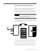
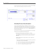
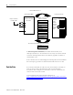
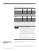
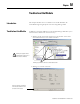
Table Of Contents
- 1732E-UM002A-EN-E 1732E EtherNet/IP ArmorBlock Supporting Sequence of Events User Manual
- Important User Information
- Table of Contents
- Preface
- Chapter 1 - About 1732E ArmorBlock Modules
- Chapter 2 - Module Overview
- Chapter 3 - Use the Module in an ArmorBlock System
- Chapter 4 - Install Your Module
- Chapter 5 - Configure the Module for Your EtherNet/IP Network
- Chapter 6 - Configure the Module Using RSLogix 5000
- Introduction
- Set Up the Hardware
- Create the Example Application
- Configure Your I/O Module
- Overview of the Configuration Process
- Add a New Bridge and Module to Your RSLogix 5000 Project
- Use the Default Configuration
- Change the Default Configuration
- Download Your Configuration
- Edit Your Configuration
- Access Module Data in RSLogix 5000
- Configure RSLogix 5000 and the 1756-EN2T Communication Module for CIP Sync
- Chapter Summary and What’s Next
- Chapter 7 - Module Features
- Introduction
- Determine Module Compatibility
- Module Features That Can Be Configured
- Chapter Summary and What’s Next
- Chapter 8 - Using the Module
- Chapter 9 - Interpret Status Indicators
- Chapter 10 - Troubleshoot the Module
- Appendix A - ArmorBlock 2 Port Ethernet Module Specifications
- Appendix B - Module Tags
- Appendix C - 1732E EtherNet/IP ArmorBlock Supporting Sequence of Events Data Tables
- Appendix D - Connect to Networks via Ethernet Interface
- Appendix E - 1732E ArmorBlock I/O Embedded Web Server
- Glossary
- Index
- How Are We Doing?
- Back Cover

Publication 1732E-UM002A-EN-P - March 2010
Using the Module 65
b. Change the NewDataAck output tag (
O.NewDataAck.x
) to a rising
edge (set the tag =1). This tag determines which inputs will be
cleared (acknowledged). There are 16 bits (x = 0…15) that can be
transitioned; each corresponding to an input. More than one bit can
be transitioned at the same time.
• If the bit = 0, change the bit to 1.
• If the bit = 1, change the bit to 0, wait for at least one RPI, and
change the bit to 1.
The corresponding I.EventOverflow and I.NewData tags are also
cleared.
• Clear all latched data for the module – This transition erases all
timestamp data from the module, clearing data from all inputs
simultaneously. Once the data is cleared, the module timestamps the
first transition in each direction for each input and sends the data to the
controller (assuming those inputs are configured with Timestamp
Capture enabled in each direction).
To clear all data for the module, transition the O.ResetEvents tag to 1.
– If the bit = 0, change the bit to 1.
– If the bit = 1, change the bit to 0, wait for at least one RPI, and
change the bit to 1.
The following figure shows when to clear data from the module. In this
example, the module sent input data to the controller, and the controller
copied the relevant input data to a separate structure. Now, the controller must
clear the data from the module.
In this example, to clear data from the module, the controller writes the
following to the Sequence of Events output word:
• O.EventAck = 1