
supporting Sequence of Events

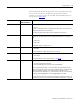
Table Of Contents
- 1732E-UM002A-EN-E 1732E EtherNet/IP ArmorBlock Supporting Sequence of Events User Manual
- Important User Information
- Table of Contents
- Preface
- Chapter 1 - About 1732E ArmorBlock Modules
- Chapter 2 - Module Overview
- Chapter 3 - Use the Module in an ArmorBlock System
- Chapter 4 - Install Your Module
- Chapter 5 - Configure the Module for Your EtherNet/IP Network
- Chapter 6 - Configure the Module Using RSLogix 5000
- Introduction
- Set Up the Hardware
- Create the Example Application
- Configure Your I/O Module
- Overview of the Configuration Process
- Add a New Bridge and Module to Your RSLogix 5000 Project
- Use the Default Configuration
- Change the Default Configuration
- Download Your Configuration
- Edit Your Configuration
- Access Module Data in RSLogix 5000
- Configure RSLogix 5000 and the 1756-EN2T Communication Module for CIP Sync
- Chapter Summary and What’s Next
- Chapter 7 - Module Features
- Introduction
- Determine Module Compatibility
- Module Features That Can Be Configured
- Chapter Summary and What’s Next
- Chapter 8 - Using the Module
- Chapter 9 - Interpret Status Indicators
- Chapter 10 - Troubleshoot the Module
- Appendix A - ArmorBlock 2 Port Ethernet Module Specifications
- Appendix B - Module Tags
- Appendix C - 1732E EtherNet/IP ArmorBlock Supporting Sequence of Events Data Tables
- Appendix D - Connect to Networks via Ethernet Interface
- Appendix E - 1732E ArmorBlock I/O Embedded Web Server
- Glossary
- Index
- How Are We Doing?
- Back Cover
Publication 1732E-UM002A-EN-P - March 2010
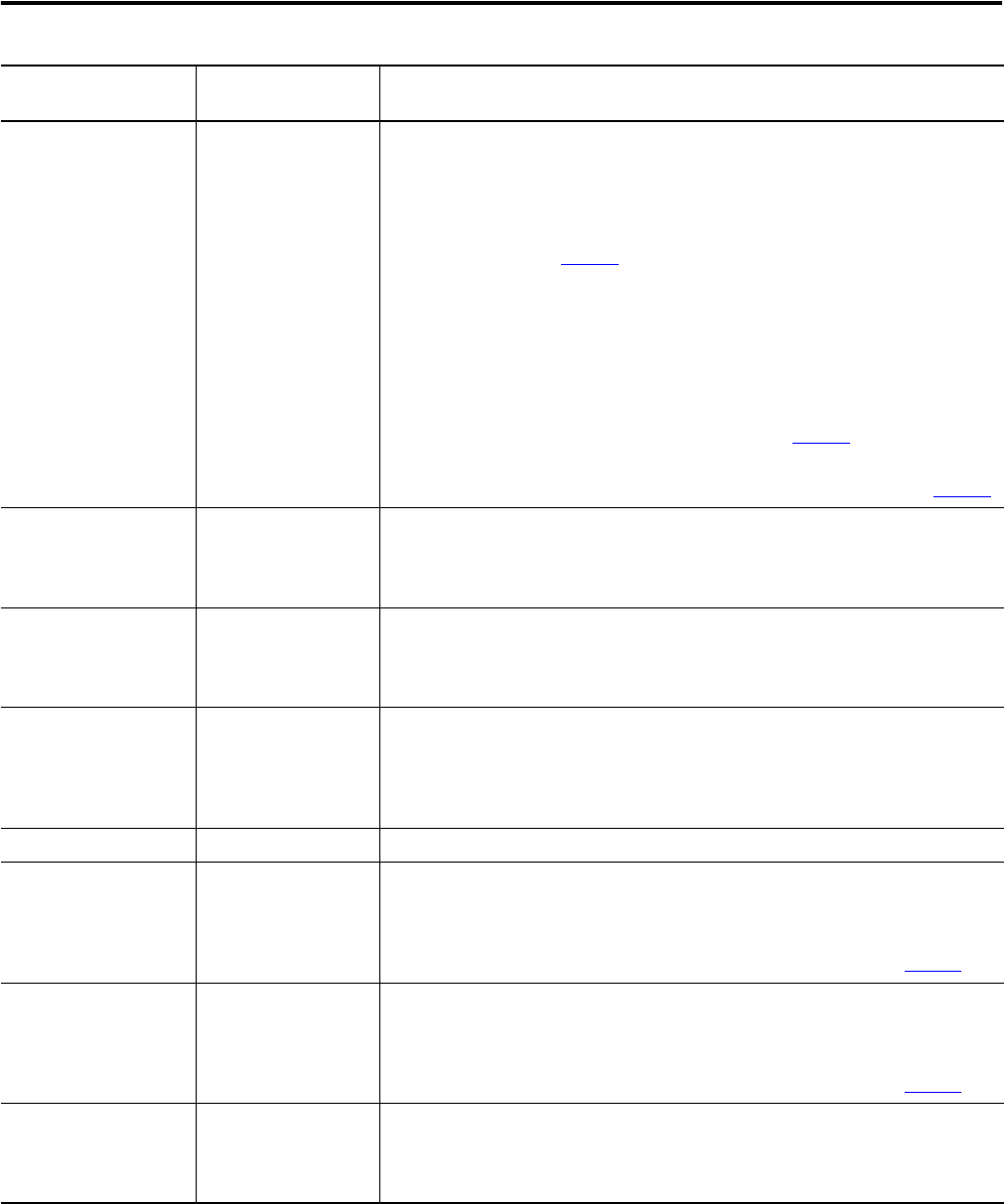
62 Using the Module
I.EventOverflow Per point Set for an input when the module either:
• Does not timestamp a transition on the input – The module has Timestamp
Latching enabled and a similar transition has already been timestamped on
this input but has not been cleared via the O.EventAck and O.NewDataAck
output tags (see page 82
).
or
• Overwrites previously-recorded timestamp data for the input – The module
has Timestamp Latching disabled and multiple transitions occur on the input.
In this case, timestamp data from new transitions are recorded before
previously-recorded transitions were cleared from the input via the
O.EventAck and O.NewDataAck output tags (see page 82
).
This tag only clears when the controller acknowledges the new data or all events on
the module are reset. For more information on clearing timestamp data, see page 64
.
I.EventNumber.x Modulewide Running count of the timestamped transitions; this tag increments by one with each
new transition that the module timestamps.
This value is cleared if the power is cycled and rolls over 1 instead of 0.
I.LocalClockOffset Modulewide The offset from the local clock to the system time. This value is useful for detecting
steps in time.
This value updates when a PTP update is received.
I.OffsetTimeStamp Modulewide The time when the PTP message was received to cause the Local Clock Offset to
update.
This value is initially zero. The first timestamp occurs when the module synchronizes
with the Grandmaster clock.
I.GrandMasterClockID Modulewide The I.D. number of the Grandmaster clock that the module is synchronized to.
I.Timestamp[16].OffOn[2] Per point Timestamp value for an input’s OFF to ON transition. This tag is a 16 x 2 32-bit array.
There is a 64-bit timestamp per point.
This value is cleared after the data has been acknowledged via the O.EventAck and
O.NewData tags. For more information on clearing timestamp data, see page 64
.
I.Timestamp[16].OnOff[2] Per point Timestamp value for an input’s ON to OFF transition. This tag is a 16 x 2 32-bit array.
There is a 64-bit timestamp per point.
This value is cleared after the data has been acknowledged via the O.EventAck and
O.NewData tags. For more information on clearing timestamp data, see page 64
.
I.SyncedToMaster Modulewide Indicates if the module is synchronized with a master clock.
1 = Synchronized
0 = Not synchronized
Tag Name Set on a Per Point or
Modulewide Basis
Description