
supporting Sequence of Events

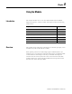
Table Of Contents
- 1732E-UM002A-EN-E 1732E EtherNet/IP ArmorBlock Supporting Sequence of Events User Manual
- Important User Information
- Table of Contents
- Preface
- Chapter 1 - About 1732E ArmorBlock Modules
- Chapter 2 - Module Overview
- Chapter 3 - Use the Module in an ArmorBlock System
- Chapter 4 - Install Your Module
- Chapter 5 - Configure the Module for Your EtherNet/IP Network
- Chapter 6 - Configure the Module Using RSLogix 5000
- Introduction
- Set Up the Hardware
- Create the Example Application
- Configure Your I/O Module
- Overview of the Configuration Process
- Add a New Bridge and Module to Your RSLogix 5000 Project
- Use the Default Configuration
- Change the Default Configuration
- Download Your Configuration
- Edit Your Configuration
- Access Module Data in RSLogix 5000
- Configure RSLogix 5000 and the 1756-EN2T Communication Module for CIP Sync
- Chapter Summary and What’s Next
- Chapter 7 - Module Features
- Introduction
- Determine Module Compatibility
- Module Features That Can Be Configured
- Chapter Summary and What’s Next
- Chapter 8 - Using the Module
- Chapter 9 - Interpret Status Indicators
- Chapter 10 - Troubleshoot the Module
- Appendix A - ArmorBlock 2 Port Ethernet Module Specifications
- Appendix B - Module Tags
- Appendix C - 1732E EtherNet/IP ArmorBlock Supporting Sequence of Events Data Tables
- Appendix D - Connect to Networks via Ethernet Interface
- Appendix E - 1732E ArmorBlock I/O Embedded Web Server
- Glossary
- Index
- How Are We Doing?
- Back Cover
Publication 1732E-UM002A-EN-P - March 2010
Using the Module 61
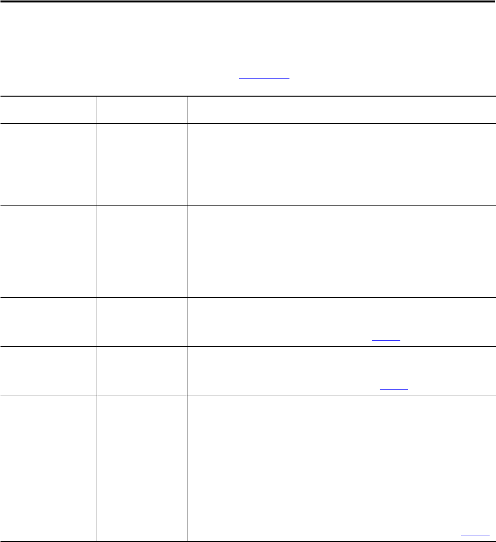
The following table describes the data that is sent for each input. These tags
are sent to the controller the next RPI after the module timestamps a
transition on any input as well as all other RPIs. For detailed descriptions of
the tags, refer to Appendix B
.
Tag Name Set on a Per Point or
Modulewide Basis
Description
I.Fault Modulewide Indicates if a communication fault has occurred.
0 = no fault
1 = fault – Communication fault - The controller sets this tag to 1 for all 32 bits if a
communication fault occurs on the module.
This tag clears when the fault that causes the condition no longer exists.
I.Data Per point Status of the input point. This data is filtered if the Input Filter feature is used on the
module. Thus, an input change must pass through the filter before it is seen in this
tag.
0 = input is OFF
1 = input is ON
For example, if input 3 is ON, I.Data.3 = 1.
I.OpenWire Per input connector 0 = no fault
1 = Open Wire
For more information on Open Wire Detection, see page 45
.
I.ShortCircuit Per input connector 0 = no fault
1 = Short Circuit
For more information on Short Circuit Protection, see page 45
.
I.NewData Per point Flag indicating if new timestamp data was detected on the input.
0 = no new timestamp data on the input
1 = new timestamp data on the input (since last acknowledged)
Because input data for all inputs is sent the RPI after each timestamped transition
and at each subsequent RPI, this tag is useful to quickly determine on which input the
transition occurred. For example, if the module sends new input data to the
owner-controller and I.NewData.5 = 1, you know that at least one of the timestamps
for input 5 (I.Timestamp[5].OffOn or I.Timestamp[5].OnOff) has new data.
This tag only clears when the controller acknowledges the new data or all events on
the module are reset. For more information on clearing timestamp data, see page 67
.