
supporting Sequence of Events

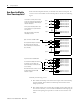
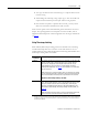
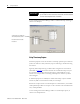
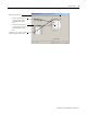
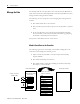
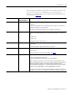
Table Of Contents
- 1732E-UM002A-EN-E 1732E EtherNet/IP ArmorBlock Supporting Sequence of Events User Manual
- Important User Information
- Table of Contents
- Preface
- Chapter 1 - About 1732E ArmorBlock Modules
- Chapter 2 - Module Overview
- Chapter 3 - Use the Module in an ArmorBlock System
- Chapter 4 - Install Your Module
- Chapter 5 - Configure the Module for Your EtherNet/IP Network
- Chapter 6 - Configure the Module Using RSLogix 5000
- Introduction
- Set Up the Hardware
- Create the Example Application
- Configure Your I/O Module
- Overview of the Configuration Process
- Add a New Bridge and Module to Your RSLogix 5000 Project
- Use the Default Configuration
- Change the Default Configuration
- Download Your Configuration
- Edit Your Configuration
- Access Module Data in RSLogix 5000
- Configure RSLogix 5000 and the 1756-EN2T Communication Module for CIP Sync
- Chapter Summary and What’s Next
- Chapter 7 - Module Features
- Introduction
- Determine Module Compatibility
- Module Features That Can Be Configured
- Chapter Summary and What’s Next
- Chapter 8 - Using the Module
- Chapter 9 - Interpret Status Indicators
- Chapter 10 - Troubleshoot the Module
- Appendix A - ArmorBlock 2 Port Ethernet Module Specifications
- Appendix B - Module Tags
- Appendix C - 1732E EtherNet/IP ArmorBlock Supporting Sequence of Events Data Tables
- Appendix D - Connect to Networks via Ethernet Interface
- Appendix E - 1732E ArmorBlock I/O Embedded Web Server
- Glossary
- Index
- How Are We Doing?
- Back Cover
Publication 1732E-UM002A-EN-P - March 2010
60 Using the Module
Manage the Data
The module sends all of its input data to the controller the next RPI after an
input transition has been timestamped and at each subsequent RPI. You must
manage the data coming from the module.
The following occurs in the process of the managing data coming from the
module:
1. The module sends data to the controller.
2. The controller copies the relevant portions of the input data to separate
array.
3. At the user’s discretion, the controller clears latched timestamp data
from the module via the O.EventAck and O.NewData tags, preparing
the module to timestamp the next transition.
This process is described in the rest of this section.
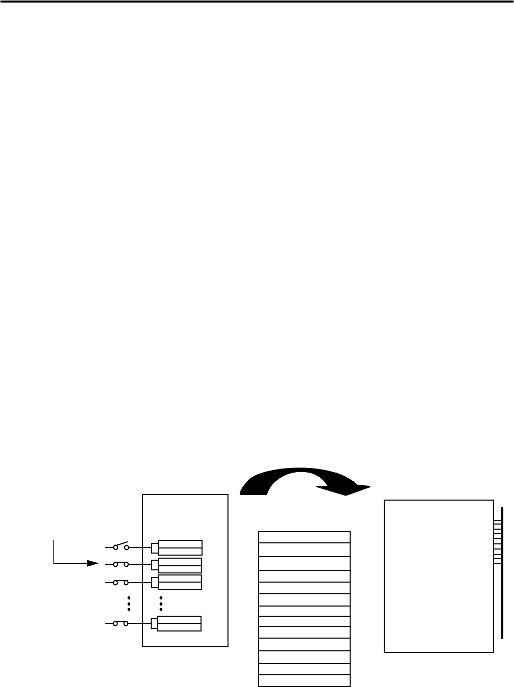
Module Sends Data to the Controller
The following figure shows an example of the module sending data to the
controller. In the example, the following occurs:
1. Input 1 transitions from OFF to ON. (The input has Timestamp
Capture enabled).
2. The module timestamps the transition.
3. The module sends its input data, including the transition timestamp
from input 1, to the controller.
1. Input 1 transitions
from OFF to ON.
2. Module timestamps
the transition.
3. Module sends input
data to the controller.
1732E-IB16M12SOEDR ControlLogix controller
I.Fault
I.EventOverflow
I.OffsetTimeStamp
I.EventNumber
I.Timestamp[16].OffOn[2]
I.Timestamp[16].OnOff[2]
I.Data
I.NewData
0 0 0 0 0 0 0
0 0 0 0 0 0 0
0 1 0 1 1 0 0
0 0 0 0 0 0 0
0 0 0 0 0 0 0
0 0 0 0 0 0 0
0 0 0 0 0 0 0
0 0 0 0 0 0 0
I.ShortCircuit
I.OpenWire
I.GrandMasterClockID
I.LocalClockOffset
I.SyncedToMaster