
supporting Sequence of Events

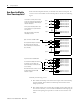
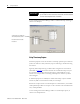
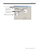
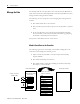
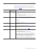
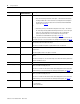
Table Of Contents
- 1732E-UM002A-EN-E 1732E EtherNet/IP ArmorBlock Supporting Sequence of Events User Manual
- Important User Information
- Table of Contents
- Preface
- Chapter 1 - About 1732E ArmorBlock Modules
- Chapter 2 - Module Overview
- Chapter 3 - Use the Module in an ArmorBlock System
- Chapter 4 - Install Your Module
- Chapter 5 - Configure the Module for Your EtherNet/IP Network
- Chapter 6 - Configure the Module Using RSLogix 5000
- Introduction
- Set Up the Hardware
- Create the Example Application
- Configure Your I/O Module
- Overview of the Configuration Process
- Add a New Bridge and Module to Your RSLogix 5000 Project
- Use the Default Configuration
- Change the Default Configuration
- Download Your Configuration
- Edit Your Configuration
- Access Module Data in RSLogix 5000
- Configure RSLogix 5000 and the 1756-EN2T Communication Module for CIP Sync
- Chapter Summary and What’s Next
- Chapter 7 - Module Features
- Introduction
- Determine Module Compatibility
- Module Features That Can Be Configured
- Chapter Summary and What’s Next
- Chapter 8 - Using the Module
- Chapter 9 - Interpret Status Indicators
- Chapter 10 - Troubleshoot the Module
- Appendix A - ArmorBlock 2 Port Ethernet Module Specifications
- Appendix B - Module Tags
- Appendix C - 1732E EtherNet/IP ArmorBlock Supporting Sequence of Events Data Tables
- Appendix D - Connect to Networks via Ethernet Interface
- Appendix E - 1732E ArmorBlock I/O Embedded Web Server
- Glossary
- Index
- How Are We Doing?
- Back Cover

Publication 1732E-UM002A-EN-P - March 2010
56 Using the Module
How Does the Module
Store Timestamp Data?
With each timestamped transition, the module stores data for that point. An
overview of how the module stores timestamp data is shown in the following
figure.
Generally the following occurs:
1. The module timestamps each transition for inputs that are Timestamp
Capture-enabled. The module can timestamp each transition with a
unique system time.
2. The module sends all of its input data, including the new data from the
most recent transition, to the controller the RPI after timestamping the
transition and passing the input filter to make sure the transition was
valid.
Input 1
Input 2
Input 15
OFF/ON timestamp data
ON/OFF timestamp data
The module is installed, wired to input
devices and ready to begin operation. All
inputs are configured to timestamp any
transition that occurs.
At this point, timestamp data for each
input is 0 because no input transitions
have occurred.
Note that only 8 bits of the 64-bit
timestamp are shown.
Input 1 transitions from OFF to ON.
The module timestamps the transition;
the module sends the data to the
owner-controller (not shown) and also
stores it locally.
Input 2 transitions from ON to OFF.
The module timestamps the transition;
the module sends the data to the
owner-controller (not shown) and also
stores it locally.
Note that the module continues to store
the timestamp for the OFF to ON
transition on input 1.
OFF/ON timestamp data
ON/OFF timestamp data
OFF/ON timestamp data
ON/OFF timestamp data
OFF/ON timestamp data
ON/OFF timestamp data
0 0 0 0 0
0 0 0 0 0
0 0 0 0 0
0 0 0 0 0
0 0 0 0 0
0 0 0 0 0
0 0 0 0 0
0 0 0 0 0
Input 0
Input 1
Input 2
Input 15
OFF/ON timestamp data
ON/OFF timestamp data
OFF/ON timestamp data
ON/OFF timestamp data
OFF/ON timestamp data
ON/OFF timestamp data
OFF/ON timestamp data
ON/OFF timestamp data
0 0 0 0 0
0 0 0 0 0
0 1 0 1 1
0 0 0 0 0
0 0 0 0 0
0 0 0 0 0
0 0 0 0 0
0 0 0 0 0
Input 0
Input 1
Input 2
Input 15
OFF/ON timestamp data
ON/OFF timestamp data
OFF/ON timestamp data
ON/OFF timestamp data
OFF/ON timestamp data
ON/OFF timestamp data
OFF/ON timestamp data
ON/OFF timestamp data
0 0 0 0 0
0 0 0 0 0
0 1 0 1 1
0 0 0 0 0
0 0 0 0 0
1 1 0 0 1
0 0 0 0 0
0 0 0 0 0
Input 0