
supporting Sequence of Events

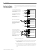
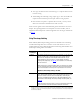
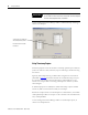
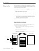
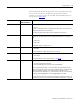
Table Of Contents
- 1732E-UM002A-EN-E 1732E EtherNet/IP ArmorBlock Supporting Sequence of Events User Manual
- Important User Information
- Table of Contents
- Preface
- Chapter 1 - About 1732E ArmorBlock Modules
- Chapter 2 - Module Overview
- Chapter 3 - Use the Module in an ArmorBlock System
- Chapter 4 - Install Your Module
- Chapter 5 - Configure the Module for Your EtherNet/IP Network
- Chapter 6 - Configure the Module Using RSLogix 5000
- Introduction
- Set Up the Hardware
- Create the Example Application
- Configure Your I/O Module
- Overview of the Configuration Process
- Add a New Bridge and Module to Your RSLogix 5000 Project
- Use the Default Configuration
- Change the Default Configuration
- Download Your Configuration
- Edit Your Configuration
- Access Module Data in RSLogix 5000
- Configure RSLogix 5000 and the 1756-EN2T Communication Module for CIP Sync
- Chapter Summary and What’s Next
- Chapter 7 - Module Features
- Introduction
- Determine Module Compatibility
- Module Features That Can Be Configured
- Chapter Summary and What’s Next
- Chapter 8 - Using the Module
- Chapter 9 - Interpret Status Indicators
- Chapter 10 - Troubleshoot the Module
- Appendix A - ArmorBlock 2 Port Ethernet Module Specifications
- Appendix B - Module Tags
- Appendix C - 1732E EtherNet/IP ArmorBlock Supporting Sequence of Events Data Tables
- Appendix D - Connect to Networks via Ethernet Interface
- Appendix E - 1732E ArmorBlock I/O Embedded Web Server
- Glossary
- Index
- How Are We Doing?
- Back Cover

55 Publication 1732E-UM002A-EN-P - March 2010
Chapter
8
Using the Module
Introduction
This chapter describes how to use the 1732E EtherNet/IP ArmorBlock
Supporting Sequence of Events module. The chapter contains the following
main sections:.
Overview
The module can be configured to timestamp two transitions per input, one in
each direction (OFF to ON and ON to OFF).
When specific points that are Timestamp Capture-enabled transition (for
example., input 1 is configured so that Timestamp Capture is enabled for OFF
to ON transitions and the input turns ON), the module timestamps the
transition with the current system time value on the network. The module
produces data for the owner-controller the RPI after the input filter criteria
have been met and at subsequent RPIs.
Topic Page
Overview 53
Manage the Data 58
Module Sends Data to the Controller 58
Copy Relevant Input Data to a Separate Data Structure 61
Acknowledge Timestamp Latching Timestamp Data 62
Sort the Data 64
Clear All Data From the Module’s Buffer At Once 65