
supporting Sequence of Events
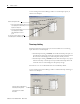
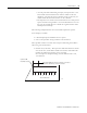
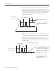
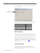
Table Of Contents
- 1732E-UM002A-EN-E 1732E EtherNet/IP ArmorBlock Supporting Sequence of Events User Manual
- Important User Information
- Table of Contents
- Preface
- Chapter 1 - About 1732E ArmorBlock Modules
- Chapter 2 - Module Overview
- Chapter 3 - Use the Module in an ArmorBlock System
- Chapter 4 - Install Your Module
- Chapter 5 - Configure the Module for Your EtherNet/IP Network
- Chapter 6 - Configure the Module Using RSLogix 5000
- Introduction
- Set Up the Hardware
- Create the Example Application
- Configure Your I/O Module
- Overview of the Configuration Process
- Add a New Bridge and Module to Your RSLogix 5000 Project
- Use the Default Configuration
- Change the Default Configuration
- Download Your Configuration
- Edit Your Configuration
- Access Module Data in RSLogix 5000
- Configure RSLogix 5000 and the 1756-EN2T Communication Module for CIP Sync
- Chapter Summary and What’s Next
- Chapter 7 - Module Features
- Introduction
- Determine Module Compatibility
- Module Features That Can Be Configured
- Chapter Summary and What’s Next
- Chapter 8 - Using the Module
- Chapter 9 - Interpret Status Indicators
- Chapter 10 - Troubleshoot the Module
- Appendix A - ArmorBlock 2 Port Ethernet Module Specifications
- Appendix B - Module Tags
- Appendix C - 1732E EtherNet/IP ArmorBlock Supporting Sequence of Events Data Tables
- Appendix D - Connect to Networks via Ethernet Interface
- Appendix E - 1732E ArmorBlock I/O Embedded Web Server
- Glossary
- Index
- How Are We Doing?
- Back Cover

Publication 1732E-UM002A-EN-P - March 2010
Module Features 47
– At some point while still filtering the input, the input returns to the
transitioned state and remains there until the module counts the
number of 1 ms intervals equal to the filter setting. In this case, the
module sends data from the transition to the controller.
– The input does not remain in the transitioned state for a time period
equal to the filter setting and the 1 ms counter decrements to zero. In
this case, the module does not consider the original transition valid
and drops the timestamp.
The following example illustrates how the module’s input filters operate.
In the example, a module:
• is Timestamp Capture-enabled for all of its points
• uses a 2 ms input filter setting for OFF to ON transitions
Three possible scenarios can result after an input transitioning from OFF to
ON in the given circumstances.
• Scenario #1 (no bounce) – The input turns ON and remains for the full
2 ms. In this case, the module considers the transition valid and sends
the data recorded at the transition to the controller.
Note the input was sampled as being on three different times: 0 ms,
1ms and 2ms.
012345678
Input turns ON;
timestamp recorded
Time in milliseconds
Input remains ON for at least 2 ms; transition is considered
valid and the timestamp is sent to the controller
43671