
supporting Sequence of Events
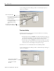
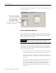
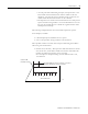
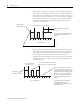
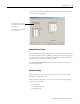
Table Of Contents
- 1732E-UM002A-EN-E 1732E EtherNet/IP ArmorBlock Supporting Sequence of Events User Manual
- Important User Information
- Table of Contents
- Preface
- Chapter 1 - About 1732E ArmorBlock Modules
- Chapter 2 - Module Overview
- Chapter 3 - Use the Module in an ArmorBlock System
- Chapter 4 - Install Your Module
- Chapter 5 - Configure the Module for Your EtherNet/IP Network
- Chapter 6 - Configure the Module Using RSLogix 5000
- Introduction
- Set Up the Hardware
- Create the Example Application
- Configure Your I/O Module
- Overview of the Configuration Process
- Add a New Bridge and Module to Your RSLogix 5000 Project
- Use the Default Configuration
- Change the Default Configuration
- Download Your Configuration
- Edit Your Configuration
- Access Module Data in RSLogix 5000
- Configure RSLogix 5000 and the 1756-EN2T Communication Module for CIP Sync
- Chapter Summary and What’s Next
- Chapter 7 - Module Features
- Introduction
- Determine Module Compatibility
- Module Features That Can Be Configured
- Chapter Summary and What’s Next
- Chapter 8 - Using the Module
- Chapter 9 - Interpret Status Indicators
- Chapter 10 - Troubleshoot the Module
- Appendix A - ArmorBlock 2 Port Ethernet Module Specifications
- Appendix B - Module Tags
- Appendix C - 1732E EtherNet/IP ArmorBlock Supporting Sequence of Events Data Tables
- Appendix D - Connect to Networks via Ethernet Interface
- Appendix E - 1732E ArmorBlock I/O Embedded Web Server
- Glossary
- Index
- How Are We Doing?
- Back Cover
Publication 1732E-UM002A-EN-P - March 2010
46 Module Features
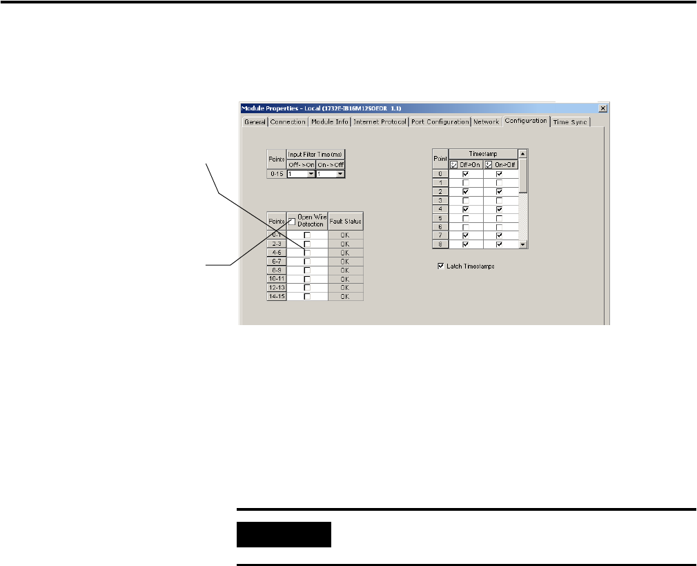
Use the Configuration tab in RSLogix 5000 to enable Open Wire Detection, as
shown in the example.
Software Configurable Input Filters
To account for hard contact “bounce”, you can configure ON to OFF and
OFF to ON input filter times in RSLogix 5000 for your module. These filters
define how long an input transition must remain in the new state before the
module considers the transition valid.
When an input transition occurs, the module timestamps the transition on the
initial edge of the transition and stores data for the transition on-board; the
module then scans the input where the transition occurred every millisecond
for the length of the filter time setting to verify that the input remains in the
new state (remained OFF or ON).
• If the input remains in the new state for a time period equal to the filter
time setting, the module sends data for the transition to the controller.
When an input transition is detected the module counts the number of
1 ms intervals the input is in the new state until the count reaches the
filter value.
• If the input changes state again (returns to the original state) before the
length of time of the filter setting has elapsed, the module starts
decrementing the number of 1 ms intervals counted until it reaches zero.
At this point the module stops filtering the input and discards the
timestamp. During this continued scan period, one of the following
events occurs:
• Click on the individual boxes for
each input point to enable Open
Wire Detection for that point.
• Clear the individual boxes for
each input point to disable Open
Wire Detection for that point.
You can also select this box to enable or
disable all points simultaneously.
IMPORTANT
Input filters are applied to all inputs on the module. You cannot
apply input filters to individual inputs on the module.