
supporting Sequence of Events
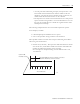
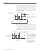
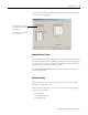
Table Of Contents
- 1732E-UM002A-EN-E 1732E EtherNet/IP ArmorBlock Supporting Sequence of Events User Manual
- Important User Information
- Table of Contents
- Preface
- Chapter 1 - About 1732E ArmorBlock Modules
- Chapter 2 - Module Overview
- Chapter 3 - Use the Module in an ArmorBlock System
- Chapter 4 - Install Your Module
- Chapter 5 - Configure the Module for Your EtherNet/IP Network
- Chapter 6 - Configure the Module Using RSLogix 5000
- Introduction
- Set Up the Hardware
- Create the Example Application
- Configure Your I/O Module
- Overview of the Configuration Process
- Add a New Bridge and Module to Your RSLogix 5000 Project
- Use the Default Configuration
- Change the Default Configuration
- Download Your Configuration
- Edit Your Configuration
- Access Module Data in RSLogix 5000
- Configure RSLogix 5000 and the 1756-EN2T Communication Module for CIP Sync
- Chapter Summary and What’s Next
- Chapter 7 - Module Features
- Introduction
- Determine Module Compatibility
- Module Features That Can Be Configured
- Chapter Summary and What’s Next
- Chapter 8 - Using the Module
- Chapter 9 - Interpret Status Indicators
- Chapter 10 - Troubleshoot the Module
- Appendix A - ArmorBlock 2 Port Ethernet Module Specifications
- Appendix B - Module Tags
- Appendix C - 1732E EtherNet/IP ArmorBlock Supporting Sequence of Events Data Tables
- Appendix D - Connect to Networks via Ethernet Interface
- Appendix E - 1732E ArmorBlock I/O Embedded Web Server
- Glossary
- Index
- How Are We Doing?
- Back Cover

Publication 1732E-UM002A-EN-P - March 2010
Module Features 45
Input Diagnostics
As with other modules with diagnostics, the input connector’s Sensor Source
Voltage (SSV), on Pin 1 of the input connectors, is protected from short
circuits to ground as well as open wire conditions due to a missing sensor or to
a cable disconnection.
Short Circuit Protection
Each connector with inputs is protected against short circuits to ground. The
circuit automatically resets each connector individually and the SSV energizes
once the short circuit is removed.
When a short circuit condition is detected, the module issues a diagnostic for a
short circuit in the module’s input tag and solid red input LEDs are illuminated
for the inputs associated with that connector. For more information on
interpreting Status Indicators, see page 69
.
Short circuit detection cannot be disabled.
Open Wire Detection
Open Wire Detection can be used to monitor each input connector for cable
disconnection conditions.
• If Open Wire Detection is enabled, the module monitors the enabled
input connectors for cable disconnections. If an open wire condition is
detected, the module issues a diagnostic for an open wire in the
module’s input tag and blinks the red diagnostic LEDs for the inputs
associated with that connector. For more information on interpreting
Status Indicators indicators, see page 69
.
• If Open Wire Detection is disabled, the module will not signal a fault for
the disabled input connectors.
Disabling Open Wire Detection on unused inputs prevents the module from
signaling a fault even though nothing is connected to it. This feature is set on
an input connector basis and is disabled for all inputs by default.