
supporting Sequence of Events
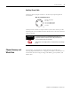

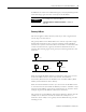
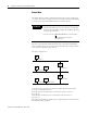
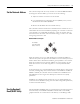
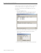
Table Of Contents
- 1732E-UM002A-EN-E 1732E EtherNet/IP ArmorBlock Supporting Sequence of Events User Manual
- Important User Information
- Table of Contents
- Preface
- Chapter 1 - About 1732E ArmorBlock Modules
- Chapter 2 - Module Overview
- Chapter 3 - Use the Module in an ArmorBlock System
- Chapter 4 - Install Your Module
- Chapter 5 - Configure the Module for Your EtherNet/IP Network
- Chapter 6 - Configure the Module Using RSLogix 5000
- Introduction
- Set Up the Hardware
- Create the Example Application
- Configure Your I/O Module
- Overview of the Configuration Process
- Add a New Bridge and Module to Your RSLogix 5000 Project
- Use the Default Configuration
- Change the Default Configuration
- Download Your Configuration
- Edit Your Configuration
- Access Module Data in RSLogix 5000
- Configure RSLogix 5000 and the 1756-EN2T Communication Module for CIP Sync
- Chapter Summary and What’s Next
- Chapter 7 - Module Features
- Introduction
- Determine Module Compatibility
- Module Features That Can Be Configured
- Chapter Summary and What’s Next
- Chapter 8 - Using the Module
- Chapter 9 - Interpret Status Indicators
- Chapter 10 - Troubleshoot the Module
- Appendix A - ArmorBlock 2 Port Ethernet Module Specifications
- Appendix B - Module Tags
- Appendix C - 1732E EtherNet/IP ArmorBlock Supporting Sequence of Events Data Tables
- Appendix D - Connect to Networks via Ethernet Interface
- Appendix E - 1732E ArmorBlock I/O Embedded Web Server
- Glossary
- Index
- How Are We Doing?
- Back Cover
Publication 1732E-UM002A-EN-P - March 2010
Configure the Module for Your EtherNet/IP Network 21
Set the Network Address
The I/O block ships with the rotary switches set to 999 and DHCP enabled.
To change the network address, you can do one of the following:
1. Adjust the switches on the front of the module.
2. Use a Dynamic Host Configuration Protocol (DHCP) server, such as
Rockwell Automation BootP/DHCP.
3. Retrieve the IP address from nonvolatile memory.
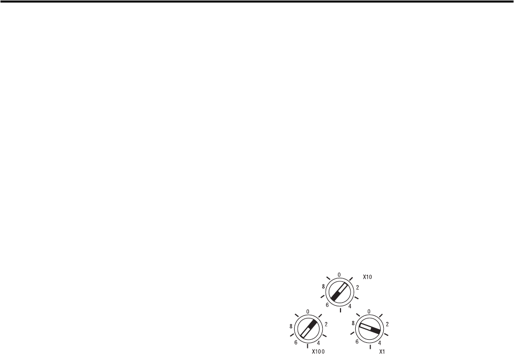
The I/O block reads the switches first to determine if the switches are set to a
valid number. Set the network address by adjusting the 3 switches on the front
of the module. Use a small blade screwdriver to rotate the switches. Line up
the small notch on the switch with the number setting you wish to use. Valid
settings range from 001…254.
Network Address Example
When the switches are set to a valid number, the I/O block’s IP address is
192.168.1.xxx (where xxx represents the number set on the switches). The I/O
block’s subnet mask is 255.255.255.0 and the gateway address is set to 0.0.0.0.
When the I/O block uses the network address set on the switches, the I/O
block does not have a host name assigned to it or use any Domain Name
Server.
If the switches are set to an invalid number (for example, 000 or a value greater
than 254, excluding 888), the I/O block checks to see if DHCP is enabled. If
DHCP is enabled, the I/O block asks for an address from a DHCP server.
The DHCP server also assigns other Transport Control Protocol (TCP)
parameters.
If DHCP is not enabled, and the switches are set to an invalid number, the
I/O block uses the IP address (along with other TCP configurable parameters)
stored in nonvolatile memory.
Use the Rockwell
BootP/DHCP Utility
The Rockwell BootP/DHCP utility is a stand alone program that incorporates
the functionality of standard BootP/DHCP software with a user-friendly
graphical interface. It is located in the Utils directory on the RSLogix 5000
This example
shows the network
address set at 163
44233