
supporting Sequence of Events
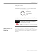

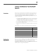
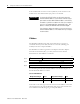
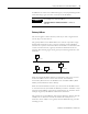
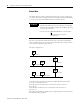
Table Of Contents
- 1732E-UM002A-EN-E 1732E EtherNet/IP ArmorBlock Supporting Sequence of Events User Manual
- Important User Information
- Table of Contents
- Preface
- Chapter 1 - About 1732E ArmorBlock Modules
- Chapter 2 - Module Overview
- Chapter 3 - Use the Module in an ArmorBlock System
- Chapter 4 - Install Your Module
- Chapter 5 - Configure the Module for Your EtherNet/IP Network
- Chapter 6 - Configure the Module Using RSLogix 5000
- Introduction
- Set Up the Hardware
- Create the Example Application
- Configure Your I/O Module
- Overview of the Configuration Process
- Add a New Bridge and Module to Your RSLogix 5000 Project
- Use the Default Configuration
- Change the Default Configuration
- Download Your Configuration
- Edit Your Configuration
- Access Module Data in RSLogix 5000
- Configure RSLogix 5000 and the 1756-EN2T Communication Module for CIP Sync
- Chapter Summary and What’s Next
- Chapter 7 - Module Features
- Introduction
- Determine Module Compatibility
- Module Features That Can Be Configured
- Chapter Summary and What’s Next
- Chapter 8 - Using the Module
- Chapter 9 - Interpret Status Indicators
- Chapter 10 - Troubleshoot the Module
- Appendix A - ArmorBlock 2 Port Ethernet Module Specifications
- Appendix B - Module Tags
- Appendix C - 1732E EtherNet/IP ArmorBlock Supporting Sequence of Events Data Tables
- Appendix D - Connect to Networks via Ethernet Interface
- Appendix E - 1732E ArmorBlock I/O Embedded Web Server
- Glossary
- Index
- How Are We Doing?
- Back Cover
Publication 1732E-UM002A-EN-P - March 2010
20 Configure the Module for Your EtherNet/IP Network
Subnet Mask
The subnet mask is used for splitting IP networks into a series of subgroups,
or subnets. The mask is a binary pattern that is matched up with the IP address
to turn part of the Host ID address field into a field for subnets.
Two bits of the Class B host ID have been used to extend the net ID. Each
unique combination of bits in the part of the Host ID where subnet mask bits
are 1 specifies a different logical network.
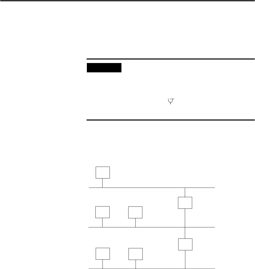
The new configuration is:
A second network with Hosts D and E was added. Gateway G2 connects
Network 2.1 with Network 2.2.
Hosts D and E use Gateway G2 to communicate with hosts not on
Network 2.2.
Hosts B and C use Gateway G to communicate with hosts not on
Network 2.1.
When B is communicating with D, G (the configured gateway for B) routes the
data from B to D through G2.
EXAMPLE
Take Network 2 (a Class B network) in the previous
example and add another network. Selecting the following
subnet mask would add two additional net ID bits, allowing
for four logical networks:
11111111 11111111 11000000 00000001 = 255.255.192.0
These two bits of the host ID used to
extend the net ID
128.2.64.1
Network 1
Network 2.1
Network 2.2
128.1.0.1
128.1.0.2
128.2.128.3
A
B
C
G
D
128.2.128.1
128.2.128.2
E
G2
128.2.64.3