
supporting Sequence of Events
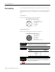
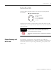

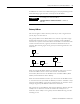
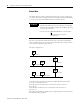
Table Of Contents
- 1732E-UM002A-EN-E 1732E EtherNet/IP ArmorBlock Supporting Sequence of Events User Manual
- Important User Information
- Table of Contents
- Preface
- Chapter 1 - About 1732E ArmorBlock Modules
- Chapter 2 - Module Overview
- Chapter 3 - Use the Module in an ArmorBlock System
- Chapter 4 - Install Your Module
- Chapter 5 - Configure the Module for Your EtherNet/IP Network
- Chapter 6 - Configure the Module Using RSLogix 5000
- Introduction
- Set Up the Hardware
- Create the Example Application
- Configure Your I/O Module
- Overview of the Configuration Process
- Add a New Bridge and Module to Your RSLogix 5000 Project
- Use the Default Configuration
- Change the Default Configuration
- Download Your Configuration
- Edit Your Configuration
- Access Module Data in RSLogix 5000
- Configure RSLogix 5000 and the 1756-EN2T Communication Module for CIP Sync
- Chapter Summary and What’s Next
- Chapter 7 - Module Features
- Introduction
- Determine Module Compatibility
- Module Features That Can Be Configured
- Chapter Summary and What’s Next
- Chapter 8 - Using the Module
- Chapter 9 - Interpret Status Indicators
- Chapter 10 - Troubleshoot the Module
- Appendix A - ArmorBlock 2 Port Ethernet Module Specifications
- Appendix B - Module Tags
- Appendix C - 1732E EtherNet/IP ArmorBlock Supporting Sequence of Events Data Tables
- Appendix D - Connect to Networks via Ethernet Interface
- Appendix E - 1732E ArmorBlock I/O Embedded Web Server
- Glossary
- Index
- How Are We Doing?
- Back Cover
Publication 1732E-UM002A-EN-P - March 2010
Configure the Module for Your EtherNet/IP Network 19
IP addresses are written as four decimal integers (0...255) separated by periods
where each integer gives the value of one byte of the IP address.
Gateway Address
This section applies to multi-network systems. If you have a single network
system, skip to the next section.
The gateway address is the default address of a network. It provides a single
domain name and point of entry to the site. Gateways connect individual
networks into a system of networks. When a node needs to communicate with
a node on another network, a gateway transfers the data between the two
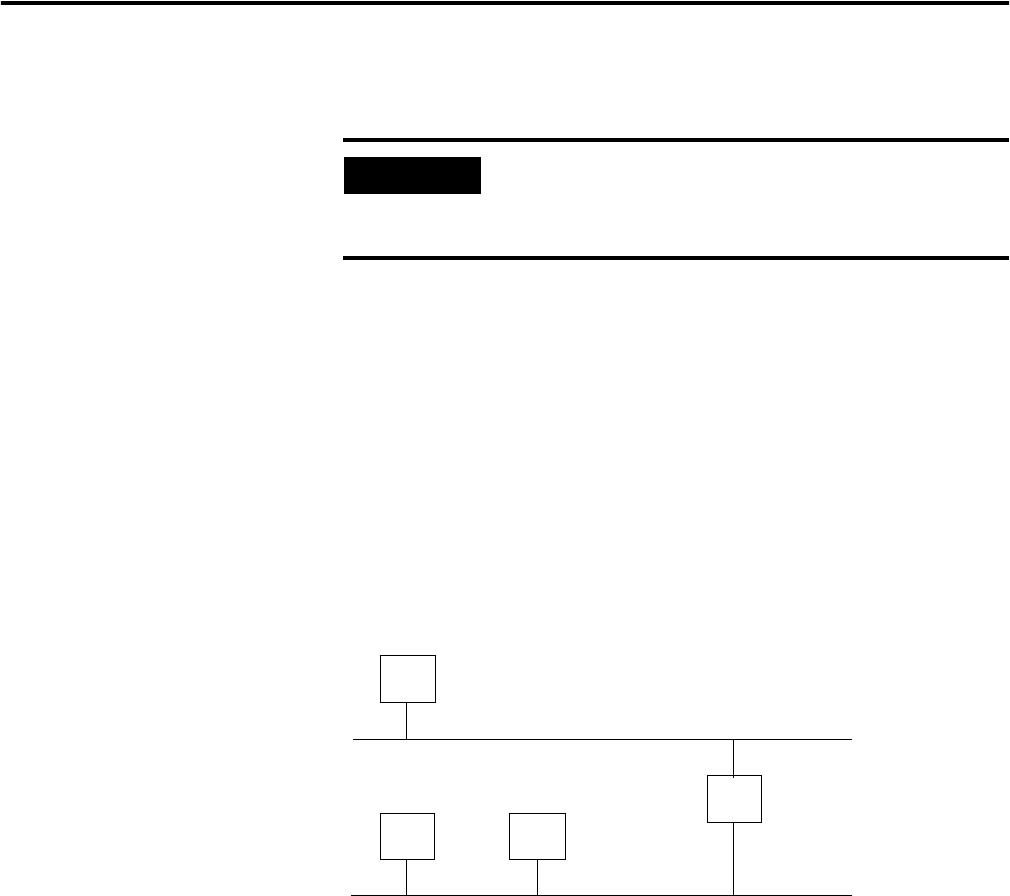
networks. The following figure shows gateway G connecting Network 1 with
Network 2.
When host B with IP address 128.2.0.1 communicates with host C, it knows
from C’s IP address that C is on the same network. In an Ethernet
environment, B then resolves C’s IP address into a hardware address (MAC
address) and communicates with C directly.
When host B communicates with host A, it knows from A’s IP address that A
is on another network (the net IDs are different). In order to send data to A, B
must have the IP address of the gateway connecting the two networks. In this
example, the gateway’s IP address on Network 2 is 128.2.0.3.
The gateway has two IP addresses (128.1.0.2 and 128.2.0.3). The first must be
used by hosts on Network 1 and the second must be used by hosts on
Network 2. To be usable, a host’s gateway must be addressed using a net ID
matching its own.
EXAMPLE
For example, the 32-bit IP address:
10000000 00000001 00000000 00000001 is written as
128.1.0.1.
Network 1
Network 2
128.2.0.3
128.1.0.2
128.1.0.1
128.2.0.1
128.2.0.2
A
B
C
G