
supporting Sequence of Events
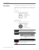

Table Of Contents
- 1732E-UM002A-EN-E 1732E EtherNet/IP ArmorBlock Supporting Sequence of Events User Manual
- Important User Information
- Table of Contents
- Preface
- Chapter 1 - About 1732E ArmorBlock Modules
- Chapter 2 - Module Overview
- Chapter 3 - Use the Module in an ArmorBlock System
- Chapter 4 - Install Your Module
- Chapter 5 - Configure the Module for Your EtherNet/IP Network
- Chapter 6 - Configure the Module Using RSLogix 5000
- Introduction
- Set Up the Hardware
- Create the Example Application
- Configure Your I/O Module
- Overview of the Configuration Process
- Add a New Bridge and Module to Your RSLogix 5000 Project
- Use the Default Configuration
- Change the Default Configuration
- Download Your Configuration
- Edit Your Configuration
- Access Module Data in RSLogix 5000
- Configure RSLogix 5000 and the 1756-EN2T Communication Module for CIP Sync
- Chapter Summary and What’s Next
- Chapter 7 - Module Features
- Introduction
- Determine Module Compatibility
- Module Features That Can Be Configured
- Chapter Summary and What’s Next
- Chapter 8 - Using the Module
- Chapter 9 - Interpret Status Indicators
- Chapter 10 - Troubleshoot the Module
- Appendix A - ArmorBlock 2 Port Ethernet Module Specifications
- Appendix B - Module Tags
- Appendix C - 1732E EtherNet/IP ArmorBlock Supporting Sequence of Events Data Tables
- Appendix D - Connect to Networks via Ethernet Interface
- Appendix E - 1732E ArmorBlock I/O Embedded Web Server
- Glossary
- Index
- How Are We Doing?
- Back Cover
Publication 1732E-UM002A-EN-P - March 2010
Install Your Module 15
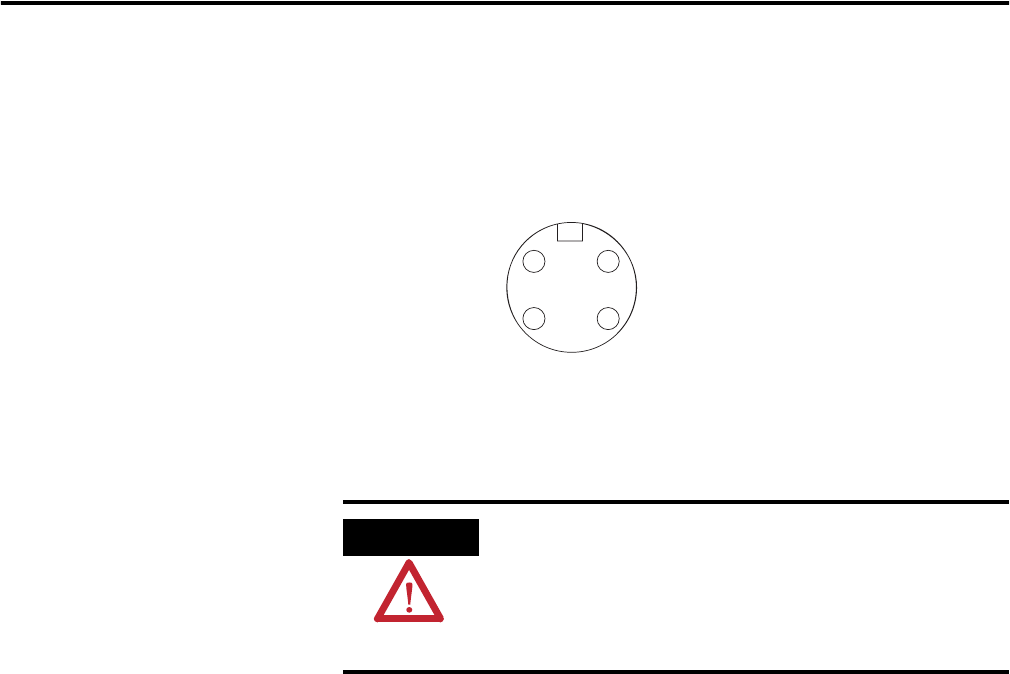
Auxiliary Power Cable
Attach the mini-style 4-pin connector to the mini-style 4-pin receptacle as
shown below.
Auxiliary Power is based on a 4-pin connector system and is used to provide
24V DC power to I/O modules and other devices. Pins 3 and 4 are connected
inside the module.
Chapter Summary and
What’s Next
In this chapter, you learned how to install and wire your module. The
following chapter describes how to configure your module to communicate on
the EtherNet/IP network by providing an IP address, gateway address, and
Subnet mask.
ATTENTION
To comply with the CE Low Voltage Directive (LVD), this
equipment and all connected I/O must be powered from a
source compliant with the following:
Safety Extra Low Voltage (SELV) or Protected Extra Low Voltage
(PELV).
4 2
3 1
Mini-style 4-Pin Male Receptacle
44809
(View into receptacle)
Pin 1 NC
Pin 2 Sensor/MDL power+
Pin 3 Sensor/MDL power-
Pin 4 NC