
supporting Sequence of Events
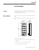
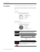
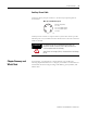

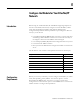
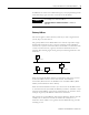
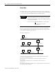
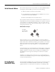
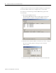
Table Of Contents
- 1732E-UM002A-EN-E 1732E EtherNet/IP ArmorBlock Supporting Sequence of Events User Manual
- Important User Information
- Table of Contents
- Preface
- Chapter 1 - About 1732E ArmorBlock Modules
- Chapter 2 - Module Overview
- Chapter 3 - Use the Module in an ArmorBlock System
- Chapter 4 - Install Your Module
- Chapter 5 - Configure the Module for Your EtherNet/IP Network
- Chapter 6 - Configure the Module Using RSLogix 5000
- Introduction
- Set Up the Hardware
- Create the Example Application
- Configure Your I/O Module
- Overview of the Configuration Process
- Add a New Bridge and Module to Your RSLogix 5000 Project
- Use the Default Configuration
- Change the Default Configuration
- Download Your Configuration
- Edit Your Configuration
- Access Module Data in RSLogix 5000
- Configure RSLogix 5000 and the 1756-EN2T Communication Module for CIP Sync
- Chapter Summary and What’s Next
- Chapter 7 - Module Features
- Introduction
- Determine Module Compatibility
- Module Features That Can Be Configured
- Chapter Summary and What’s Next
- Chapter 8 - Using the Module
- Chapter 9 - Interpret Status Indicators
- Chapter 10 - Troubleshoot the Module
- Appendix A - ArmorBlock 2 Port Ethernet Module Specifications
- Appendix B - Module Tags
- Appendix C - 1732E EtherNet/IP ArmorBlock Supporting Sequence of Events Data Tables
- Appendix D - Connect to Networks via Ethernet Interface
- Appendix E - 1732E ArmorBlock I/O Embedded Web Server
- Glossary
- Index
- How Are We Doing?
- Back Cover
Publication 1732E-UM002A-EN-P - March 2010
14 Install Your Module
Wire the Module
The ArmorBlock EtherNet/IP family has 5-pin micro-style I/O connectors.
We provide caps to cover the unused connectors on your module. Connect the
quick-disconnect cord sets you selected for your module to the appropriate
ports.
I/O Connectors
Refer to the pinout diagrams for the I/O connectors.
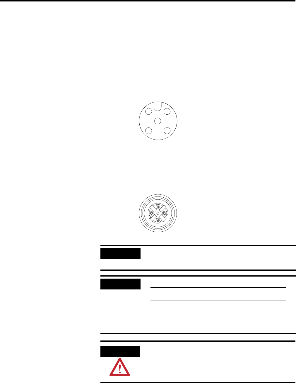
Ethernet/IP Connectors
Refer to the pinout diagrams for the network connectors.
.
IMPORTANT
Use the 1585D–M4DC–H: Polyamide small body unshielded or the
1585D–M4DC–SH: Zinc die-cast large body shielded mating
connectors for the D-Code M12 female network connector.
IMPORTANT
Use two twisted pair CAT5E UTP or STP cable.
ATTENTION
Make sure all connectors and caps are securely tightened to
properly seal the connections against leaks and maintain IP
enclosure type requirements.
1 2
4
5
3
(View into connector)
Pin 1 Sensor Source Voltage
Pin 2 Input B
Pin 3 Return
Pin 4 Input A
Pin 5 PE
Micro-style
5-Pin Input
Female
Connector
44807
4
2
31
5
D-Code M12 Network Female Connector
44808
(View into connector)
Pin 1 M12_Tx+
Pin 2 M12_Rx+
Pin 3 M12_Tx-
Pin 4 M12_Rx-
Pin 5 Connector shell shield FE
D-Code
M12 Pin
Wire Color Signal 8-way Modular
RJ45 Pin
1 White-Orange TX+ 1
2 White-Green RX+ 3
3 Orange TX- 2
4 Green RX- 6