
supporting Sequence of Events
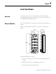
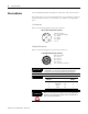

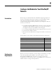
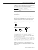
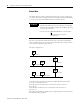
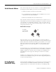
Table Of Contents
- 1732E-UM002A-EN-E 1732E EtherNet/IP ArmorBlock Supporting Sequence of Events User Manual
- Important User Information
- Table of Contents
- Preface
- Chapter 1 - About 1732E ArmorBlock Modules
- Chapter 2 - Module Overview
- Chapter 3 - Use the Module in an ArmorBlock System
- Chapter 4 - Install Your Module
- Chapter 5 - Configure the Module for Your EtherNet/IP Network
- Chapter 6 - Configure the Module Using RSLogix 5000
- Introduction
- Set Up the Hardware
- Create the Example Application
- Configure Your I/O Module
- Overview of the Configuration Process
- Add a New Bridge and Module to Your RSLogix 5000 Project
- Use the Default Configuration
- Change the Default Configuration
- Download Your Configuration
- Edit Your Configuration
- Access Module Data in RSLogix 5000
- Configure RSLogix 5000 and the 1756-EN2T Communication Module for CIP Sync
- Chapter Summary and What’s Next
- Chapter 7 - Module Features
- Introduction
- Determine Module Compatibility
- Module Features That Can Be Configured
- Chapter Summary and What’s Next
- Chapter 8 - Using the Module
- Chapter 9 - Interpret Status Indicators
- Chapter 10 - Troubleshoot the Module
- Appendix A - ArmorBlock 2 Port Ethernet Module Specifications
- Appendix B - Module Tags
- Appendix C - 1732E EtherNet/IP ArmorBlock Supporting Sequence of Events Data Tables
- Appendix D - Connect to Networks via Ethernet Interface
- Appendix E - 1732E ArmorBlock I/O Embedded Web Server
- Glossary
- Index
- How Are We Doing?
- Back Cover
13 Publication 1732E-UM002A-EN-P - March 2010
Chapter
4
Install Your Module
Overview
This chapter shows you how to install and wire the 1732E EtherNet/IP
ArmorBlock Supporting Sequence of Events. The only tools you require are a
flat or Phillips head screwdriver and drill.
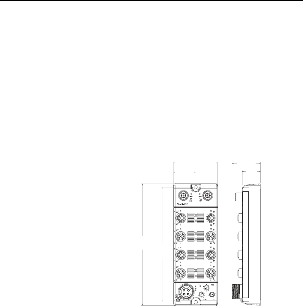
Mount the Module
To mount the module on a wall or panel, use the screw holes provided in the
module.
Refer to the drilling dimensions illustration to guide you in mounting the
module.
Install the mounting base as follows:
1. Lay out the required points as shown above in the drilling dimension
drawing.
2. Drill the necessary holes for #8 (M4) pan head screws.
3. Mount the module using #8 (M4) screws.
44946
179 mm
(7.05 in.)
169 mm
(6.64 in.)
65 mm
(2.56 in.)
43.25 mm
(1.70 in.)
26.5 mm
(1.04 in.)
Front view
Side view
32.5 mm
(1.28 in.)