
Manual

Publication 1732D-IN001B-EN-E - May 2004
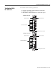
DeviceNet 1732 ArmorBlock I/O, Series A 13
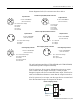
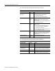
The following table describes the auxiliary power indicator.
The following table describes individual I/O status indicators.
This product has been tested at an Open DeviceNet Vendor
Association, Inc. (ODVA) authorized independent test laboratory and
found to comply with ODVA Conformance Test. Please contact the
ODVA website (http://www.odva.org) for listing of products tested by
ODVA independent test labs for further details.
Specifications
Following are specifications for the 1732 ArmorBlock I/O modules.
Auxiliary Power
Indication Status
None No Auxiliary Power
Solid Green Auxiliary Power Present
I/O Status Indicators
Function Point Indicator Condition
Outputs None
Yellow
Output not energized
Output energized
Inputs None
Yellow
No valid input
Valid input
DeviceNet 1732 ArmorBlock I/O Series A
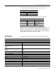
Input Specifications
Inputs 61131-2 Type 3 Compatible
Sensor Source Current, Maximum (per input) 50mA
Sensor Source Current, Maximum (per module) 400mA
Sensor Source Voltage
(auxiliary power=12-30V dc)
Maximum
Minimum
30V
11V
On-state Voltage
Maximum
Minimum
30V dc
11V dc
On-state Current, Maximum 5mA
Off-state Voltage, Maximum 5V dc
Off-state Current, Maximum 1.5mA
Input Delay Time - ON to OFF and OFF to ON, Maximum 0-16000 µs
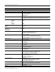
Output Specifications
Outputs 61131-2 Compatible
Off-state Peak Blocking Voltage, Minimum 30V
On-state Voltage Drop, Maximum 0.5V
On-state Current, Maximum 0.5A
Off-state Leakage, Maximum 50µA
Module Current, Maximum (all outputs) 4.0A
Surge Current for 10ms, repeatable every 2s, Maximum 1.2A