Installation Instructions DeviceNet ArmorBlock Network and Auxiliary Powered Module, Series A Catalog Number 1732D-8X81212HD Topic Page Important User Information 2 Environment and Enclosure 3 Prevent Electrostatic Discharge 3 About the Module 4 Catalog Number Explanation 5 Install the Module 5 Mount the Module 6 Communicate with Your Module 11 Interpret the Status Indicators 12 Specifications 15
DeviceNet ArmorBlock Network and Auxiliary Powered Module, Series A Important User Information Solid state equipment has operational characteristics differing from those of electromechanical equipment. Safety Guidelines for the Application, Installation and Maintenance of Solid State Controls (Publication SGI-1.1 available from your local Rockwell Automation sales office or online at http://literature.rockwellautomation.
DeviceNet ArmorBlock Network and Auxiliary Powered Module, Series A 3 Environment and Enclosure ATTENTION This equipment is intended for use in overvoltage Category II applications (as defined in IEC 60664-1), at altitudes up to 2000 m (6562 ft) without derating. This equipment is considered Group 1, Class A industrial equipment according to IEC/CISPR 11.
DeviceNet ArmorBlock Network and Auxiliary Powered Module, Series A About the Module The DeviceNet 1732D ArmorBlock I/O family consists of stand-alone 24V DC I/O modules that communicate via the DeviceNet network. The sealed IP69K housing of these modules requires no enclosure. Note that it is possible that environmental requirements other than IP69K require an additional appropriate enclosure. I/O connectors are sealed M12 style.
DeviceNet ArmorBlock Network and Auxiliary Powered Module, Series A 5 Catalog Number Explanation The catalog number 1732D-8X81212HD identifies a DeviceNet 24V DC 8-port 8-input 8-output 1.4 A M12-style network connector module. Install the Module To install the module: • Set the node address • Mount the module • Connect the cord sets Set the Node Address Valid node addresses are 00 through 63.
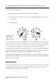
DeviceNet ArmorBlock Network and Auxiliary Powered Module, Series A To reset the node address: 1. Rotate the switches using a small blade screwdriver. 2. Line up the small black dot on the switch with the number setting you wish to use. 3. Cycle power. Example shows default node address set at 63. 43968 The rotary switches are read periodically.
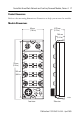
DeviceNet ArmorBlock Network and Auxiliary Powered Module, Series A 7 Product Dimensions Refer to the mounting dimensions illustration to help you mount the module. Module Dimensions 65 mm (2.56 in.) 43.25 mm (1.70 in.) 26.5 mm (1.04 in.) DNet In DNet Out MOD NET I-0 O-0 I-1 O-1 I-2 O-2 179 mm (7.05 in.) 169 mm (6.64 in.
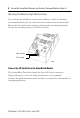
DeviceNet ArmorBlock Network and Auxiliary Powered Module, Series A Mounting the Module in High Vibration Areas If you mount the module in an area that is subject to shock or vibration, we recommend that you use a flat and a lock washer to mount the module. Mount the flat and the lock washer as shown in the mounting illustration. Torque the mounting screws to 0.64 Nm (6 in-lb).
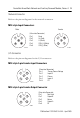
DeviceNet ArmorBlock Network and Auxiliary Powered Module, Series A 9 Network Connector Refer to the pinout diagram for the network connector. M12-style Input Connectors Male Female (View into Connector) Pin 1 Drain Pin 2 V+ (Red) Pin 3 V- (Black) Pin 4 CAN_H (White) Pin 5 CAN_L (Blue) 44175 41452 I/O Connectors Refer to the pinout diagrams for the I/O connectors.
DeviceNet ArmorBlock Network and Auxiliary Powered Module, Series A Auxiliary Power Cable Refer to the pinout diagram to attach auxiliary power. M18-style 4-pin Male Auxiliary Power Connector 4 2 3 1 (View into Connector) Pin 1 Output Power+ Pin 2 No Connection Pin 3 No Connection Pin 4 Output Power43906 Refer to publication M116-CA001 for Rockwell Automation cable and cord set offerings or access the Connection Systems website at http://www.ab.com/sensors/products/connection_systems/.
DeviceNet ArmorBlock Network and Auxiliary Powered Module, Series A 11 Communicate with Your Module This module’s I/O is exchanged with the master through a cyclic, polled, or change-of-state connection. Cyclic - allows configuration of the block as an I/O client. The block will produce and consume its I/O cyclically at the rate configured. Polled - a master initiates communication by sending its polled I/O message to the module. The module consumes the message, updates outputs, and produces a response.
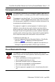
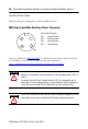
DeviceNet ArmorBlock Network and Auxiliary Powered Module, Series A Interpret the Status Indicators This module has the following status indicators: • Network and Module status indicators for DeviceNet • Auxiliary Power indicator • Individual I/O status indicators for inputs and outputs DNet In Module status indicator Input status indicators DNet Out MOD Network status indicator NET I-0 O-0 I-1 O-1 I-2 O-2 I-3 O-3 I-4 O-4 I-5 O-5 I-6 O-6 Output status indicators O-7 I-7 P W R 0
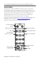
DeviceNet ArmorBlock Network and Auxiliary Powered Module, Series A 13 Network Status Status Description Recommended action Off Device is not online. Wait until the device has completed the dup_MAC_id test or apply power to the device. Green Device is operating normally and is online with connections in the established state. As a Group 2 module, it means that the module is allocated to a master. None. Flashing Green Device is online with no connections in the established state.
DeviceNet ArmorBlock Network and Auxiliary Powered Module, Series A Module Status Status Description Recommended action Off There is no power applied to the device. Apply power to the device. Green Device is operating normally. None. Flashing Green Device needs commissioning due to missing, incomplete, or incorrect configuration. Check your configuration and cycle power. Flashing Red Recoverable fault – input or output short circuit.
DeviceNet ArmorBlock Network and Auxiliary Powered Module, Series A 15 Specifications DeviceNet 1732 ArmorBlock Network Powered and Auxiliary Powered Output Module, Series A - 1732D-8X81212HD Inputs Attribute Value Number of inputs 8 Off-state input voltage, max 5V DC On-state input voltage, max 25V DC On-state input voltage, nom 24V DC On-state input voltage, min 11V DC Sensor source voltage, max 25V DC Sensor source voltage, min 11V DC Off-state input current, max 1.
DeviceNet ArmorBlock Network and Auxiliary Powered Module, Series A DeviceNet 1732 ArmorBlock Network Powered and Auxiliary Powered Output Module, Series A - 1732D-8X81212HD Outputs Attribute Value Number of outputs 8 On-state output voltage drop, max 0.5V DC Off-peak blocking voltage, min 30V DC On-state output voltage, max 30V DC On-state output voltage, min 11V DC On-state output voltage, nom 24V DC On-state output current, max 1.
DeviceNet ArmorBlock Network and Auxiliary Powered Module, Series A 17 General Specifications (Continued) Attribute Value DeviceNet power voltage, min 11V DC DeviceNet current 100 mA plus sum of sensor currents Sensor source current per module, max 500 mA Communication rate 125 Kbps @ 500 m (1640 ft) for thick cable, flat media length 375 m (1230 ft) 250 Kbps @ 200 m (600 ft) for thick cable, flat media length 150 m (492 ft) 500 Kbps @ 100 m (330 ft) for thick cable, flat media length 75 m (246 ft)
DeviceNet ArmorBlock Network and Auxiliary Powered Module, Series A Environmental Specifications Attribute Value Temperature, operating IEC 60068-2-1 (Test Ad, Operating Cold), IEC 60068-2-2 (Test Bd, Operating Dry Heat), IEC 60068-2-14 (Test Nb, Operating Thermal Shock): -20…60 °C (-4…140 °F) Temperature, non-operating IEC 60068-2-1 (Test Ab, Unpackaged Non-operating Cold), IEC 60068-2-2 (Test Bb, Unpackaged Non-operating Dry Heat), IEC 60068-2-14 (Test Na, Unpackaged Non-operating Thermal Shock):
DeviceNet ArmorBlock Network and Auxiliary Powered Module, Series A 19 Environmental Specifications (Continued) Attribute Value EFT/B Immunity IEC 61000-4-4: ±3 kV at 5 kHz on power ports ±3 kV at 5 kHz on signal ports ±2 kV at 5 kHz on communications ports Surge transient immunity IEC 61000-4-5: ±1 kV line-line(DM) and ±2 kV line-earth(CM) on power ports ±1 kV line-line(DM) and ±2 kV line-earth(CM) on signal ports ±2 kV line-earth(CM) on communications ports Conducted RF immunity IEC 61000-4-6: 10V
DeviceNet ArmorBlock Network and Auxiliary Powered Module, Series A Certifications Certification (when Value product is marked)(1) c-UL-us UL Listed Industrial Control Equipment, certified for US and Canada. See UL File E322657. CE European Union 2004/108/EC EMC Directive, compliant with: EN 61326-1; Meas./Control/Lab.
DeviceNet ArmorBlock Network and Auxiliary Powered Module, Series A 21 Notes: Publication 1732D-IN011A-EN-E - April 2009
DeviceNet ArmorBlock Network and Auxiliary Powered Module, Series A Notes: Publication 1732D-IN011A-EN-E - April 2009
DeviceNet ArmorBlock Network and Auxiliary Powered Module, Series A 23 Notes: Publication 1732D-IN011A-EN-E - April 2009
Rockwell Automation Support Rockwell Automation provides technical information on the Web to assist you in using its products. At http://support.rockwellautomation.com, you can find technical manuals, a knowledge base of FAQs, technical and application notes, sample code and links to software service packs, and a MySupport feature that you can customize to make the best use of these tools.