
User Manual Owner manual

Rockwell Automation Publication 1715-UM001C-EN-P - March 2014 91
Installation Instructions Chapter 2
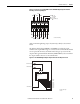
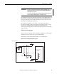
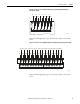
Figure 39 - Connections to 1715-TASOB8DE and 1715-TADOB8DE Digital Output Termination
Assembly 8-channel Simplex/Duplex
Apply a minimum tightening torque of 0.5 N•m (0.37 lb•ft) to the terminal
screws.
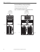
The 24V DC field voltages VFIELD 1 and VFIELD 2, used by the output
module for the output field voltages, are connected at the terminal blocks and fed
via two replaceable 10 A fuses, F1 and F2. These fuses give protection for the
output module against field faults. Field OV (VFIELD RTN) is also routed from
the output module connectors to the terminal block.
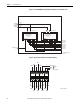
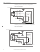
Figure 40 - 1715-TASOB8DE Digital Output Simplex Termination Assembly Connections
OV OV OV
V1
+
+
V2
V1 +
V2 +
OV
To
Next
TA
(if tted)
TB1 TB2 TB3 TB4
CH0 CH2 CH4 CH6
CH1 CH3 CH5 CH7
32105-M DO TA Field Wiring
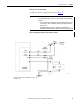
VFIELD1+24V DC
VFIELD2+24V DC
VFIELD RTN OV
DO CH0
DO CH1
DO CH2
DO CH3
DO CH4
DO CH5
DO CH6
DO CH7
F2
F1
Digital Output Module
Fail Safe Channel
Array
32103-M DO Simplex Output
Connections