
User Manual Owner manual

84 Rockwell Automation Publication 1715-UM001C-EN-P - March 2014
Chapter 2 Installation Instructions
Field Wiring of Digital Input Termination Assemblies
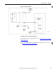
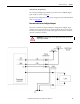
The termination assembly routes each digital input through a circuit. See
Figure 33
. The input channel is protected with a 50 mA fuse. When an extreme
over-voltage is applied to the input, the fuse blows. Each digital input signal is
terminated by 5.11 khigh reliability load and is fed to the input module’s input
circuit.
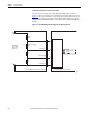
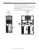
Figure 33 - 1715-TASIB16D Digital Input Termination Assembly Input Circuit
+ve
4K99
F1
24V Digital
Field Input
Channel
50 mA Time Lag
Fuse
100
20
-ve
1715-TASIB16D- Termination Assembly
J1/J2
OV Common
500 mV Range
2.5V Range
1715-IB16D Digital Input Module
Power & Signal
Isolator
M
32101-M