
User Manual Owner manual

70 Rockwell Automation Publication 1715-UM001C-EN-P - March 2014
Chapter 2 Installation Instructions
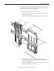
Mount I/O Expansion Cable
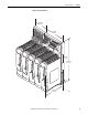
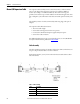
The expansion cable assembly connects an I/O base unit to another I/O base
unit or to the adapter base unit. It lets extra I/O to be added at a different
location (for example, on a different DIN rail). The cable is 2 m long and
provides connection for up to 24 I/O modules. The maximum length of an entire
bus, or backplane, (the combination of I/O base units and expansion cables) is 10
m.
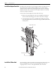
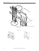
The assembly consists of a cable, terminated by multi-way plugs, and a pair of
adapters.
The expansion cable offers these features:
• Two -meter cable leng th
• Secure with retaining screws and screw cap screws
• Connects all command and response signals and system power
• Screened to reduce emissions
For additional information on pin-out and pin allocations, see 1715 Redundant
I/O System Technical Data, publication 1715-TD001
.
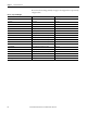
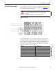
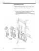
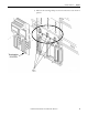
Cable Assembly
The cable assembly is made up of a SCSI-3 cable and two ferrites. The ferrites are
snap-on components that reduce resonance emissions.
Fit the ferrites 50 mm (1.97 in.) from each end and secure with cable ties either
side of the ferrites.
Table 9 - Cable Assembly
32080-M
Item Description
1 SCSI-3 cable
2 Ferrite
3 Cable-tie