
User Manual Owner manual

60 Rockwell Automation Publication 1715-UM001C-EN-P - March 2014
Chapter 2 Installation Instructions
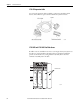
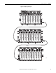
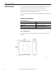
DIN Rail Assembly
The 1715 Redundant I/O System is mounted on DIN rails within an enclosure.
Pay special attention to dimensions needed for base unit placement.
For each pair of DIN rails, mount the lower rail with its center line 101 mm
(3.98 in.) below the center line of the upper rail.
Free space must also be provided on each end of the DIN rail for the end stops, if
required.
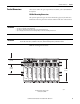
Component Size and Weights
The total depth of a base unit and module is 136 mm (5.375 in.).
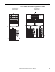
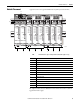
Figure 23 - Module Dimensions
All module dimensions are the same, whether they are adapter modules or I/O
modules.
Table 7 - Component Sizes
Item Size (H x W x D)
Adapter base unit 224 x 84 x 30 mm (8.82 x 3.31 x 1.18 in.)
I/O module base unit 233 x 126 x 18 mm (9.25 x 5 x .75 in.)
Module 166 x 42 x 118 mm (6.5 x 1.625 x 4.625 in.)
32067-M