
User Manual Owner manual

308 Rockwell Automation Publication 1715-UM001C-EN-P - March 2014
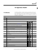
Appendix G I/O Tag Definitions
1715-OB8DE
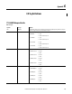
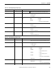
Table 78 - 16-channel Digital Input, Duplex
Tag Name Data Type Definition
Fault DINT, Binary Module fault bit: 0 when one module is present and reporting valid data, OxFFF_FFFF when no
modules are present, no Logix connection exists, or reported data is invalid.
Data INT Input state, one bit per channel for channels 0…15:
0 = Off/de-energized
1 = On, energized
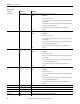
Status DINT, bit-field Redundancy and power status:
Bit Name Description
0 ModAFault 0 = Good
1 = Fault or module not present
1 ModBFault 0 = Good
1 = Fault or module not present
8 GroupFault 0 = Good
1 = Any channel or module faulted/failed
9 ModAGroupFault 0 = Good
1 = Any channel or module A faulted/failed
10 ModBGroupFault 0 = Good
1 = Any channel or Module B faulted/failed
PtFault INT Channel fault status; one bit per channel for channels 0…15:
0 = Normal
1 = Channel is faulted/failed
Open Wire INT Open wire diagnostic status; one bit per channel for channels 0…15:
0 = Normal
1 = Indicates open wire detected
ShortCircuit INT Short circuit diagnostic status; one bit per channel for channels 0…15:
0 = Normal
1 = Indicates short circuit detected
Indeterminate INT Indeterminate diagnostic status; one channel per channel for channels 0…15:
0 = Normal
1 = Indicates indeterminate input voltage detected
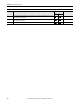
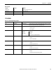
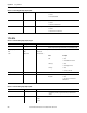
Table 79 - 8-channel Digital Output, Simplex, Output
Tag Name Data Type Definition
Data SINT Output channel commanded data; one bit per channel for channels 0…7:
0 = Off/de-energize
1 = On/energize
AlarmUnlatch SINT Unlatch alarm; one bit per channel for channels 0…7; rising edge transition (that is, 0>1)
ResetBlownFuse SINT Reset blown electronic fuse, one bit per channel for channels 0…7; rising edge transition (that is, 0>1) resets